I am currently working on a vehicle-installed Arduino project. The device is designed to be powered constantly and I decided to use the car battery as the constant power source. I am designing the device for low power consumption, consuming 50mA or less, ’cause who wants to get stuck with a flat battery, right?
Car battery typically provides 7 to 15 volts, but some standards mention that 40V spikes are possible. Car battery voltage is normally around 12V but drops to ~7V when you are cranking up the engine and it goes up to ~14V when the engine is running and the battery is being charged. Since we don’t want our device to reset during crank-ups we would like to perform conversion of input voltage of 7 to 20 volts to a fixed 5 volts output that the Arduino Uno expects.
Voltage regulators
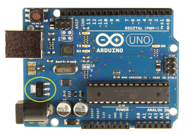
The Arduino Uno has a voltage regulator on board which we could use. It is recommended for voltages between 7 and 12 volts. This means that we would have to lower the car battery high voltage first with an external component before we can feed it in the Arduino Uno board. Unfortunately, that alone would not solve our problems as it would not address our efficiency requirements.
To perform an efficient conversion, we would have to use a switching power supply, specifically a buck converter, which will step down the voltage for us. A buck converter will turn the input on and off quickly as much as needed to provide the required voltage and power at the output. The rest of this article will compare six different step-down (buck) modules. If you are not familiar with how a switching-mode step-down converter works, read this article which also compares some modules at higher loads.
Candidate modules
One implementation that I considered is to drop the battery voltage to around 7 volts and then power the Arduino through its voltage regulator. The advantage is a more stable voltage for the Arduino, however, there would be waste of energy of 1-eff(reg)=1-5/7=28%. Furthermore, every conversion process requires some margin between Vin and Vout, so by having two stages it becomes difficult for us to support the lower end of the car battery voltage range, creating potential issues with resets during engine cranking.
So I ended up looking for modules that can take the car battery range and output 5 volts. This could be an adjustable module or one fixed at 5 volts. I would connect those modules to an Arduino USB port (preferred due to additional protections present there) or directly to an Arduino 5V pin. This means that there is some preference to modules with a built-in female USB output port, though adapters or converter cables can be made to compensate for lack of it.
Modules
The modules I tested originate from the Far East and most of them were bought on eBay for between 1 and 2 USD (including shipping). This means that most of them don’t have a clear model number or a manufacturer name. I will come up with a short name for each module so I can mention them easily. I acknowledge that the quality of the photos could be better. I tried my best with the equipment I had available. Also note that each photo is at it’s own scale. Here are the modules in no particular order.
Cigar
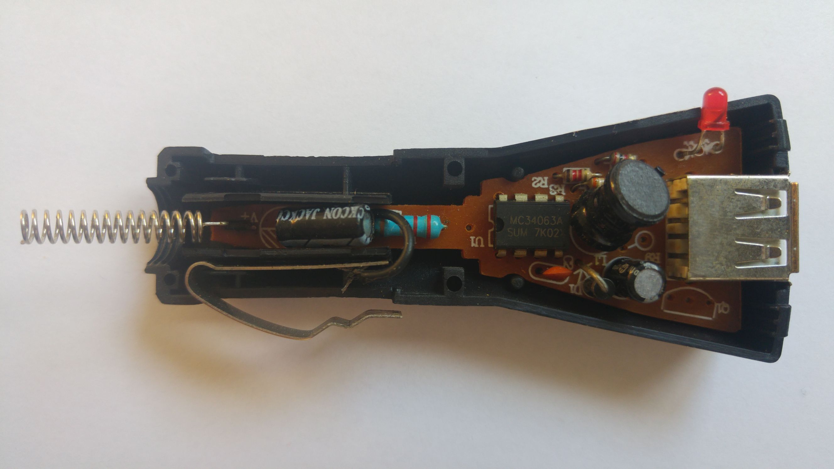
This adapter has a cigar lighter plug on one end and is built for plugging into to the cigar lighter socket in a car. The output socket is a female USB port. Such modules are sold to end users for charging USB devices in a car. I have no idea where I got this, but I found it in my parts bin, took it apart and used it in this research.
Since such converters are sold to end users, their listings typically don’t show a photo of the PCB, so it is a roulette with regards to what chip and efficiency you are getting.
Adjustable
This adapter was sold on eBay as “DC-DC Adjustable Step-down Power Module LM2596 4.75-24V To 0.93-18V”. In reality, there is no LM2596 chip there, something that shouldn’t be a huge surprise for eBay shoppers out there. It IS an adjustable step-down module which is great for prototyping. You adjust the output voltage with the multi-turn potentiometer. The input and output connectors are screw terminals and you can see I have connected them to a barrel plug for convenient use.
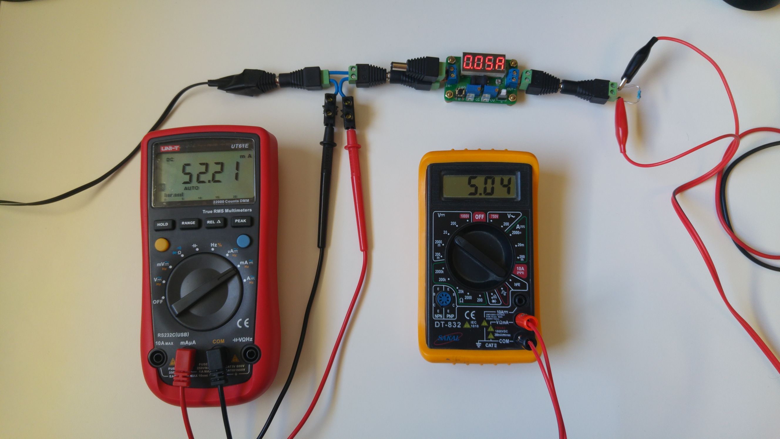
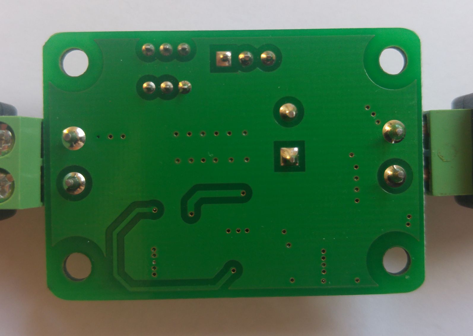
Ammeter
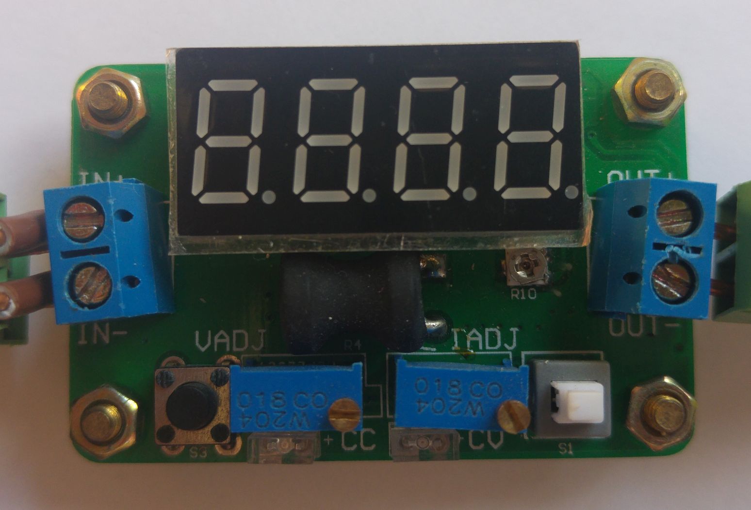
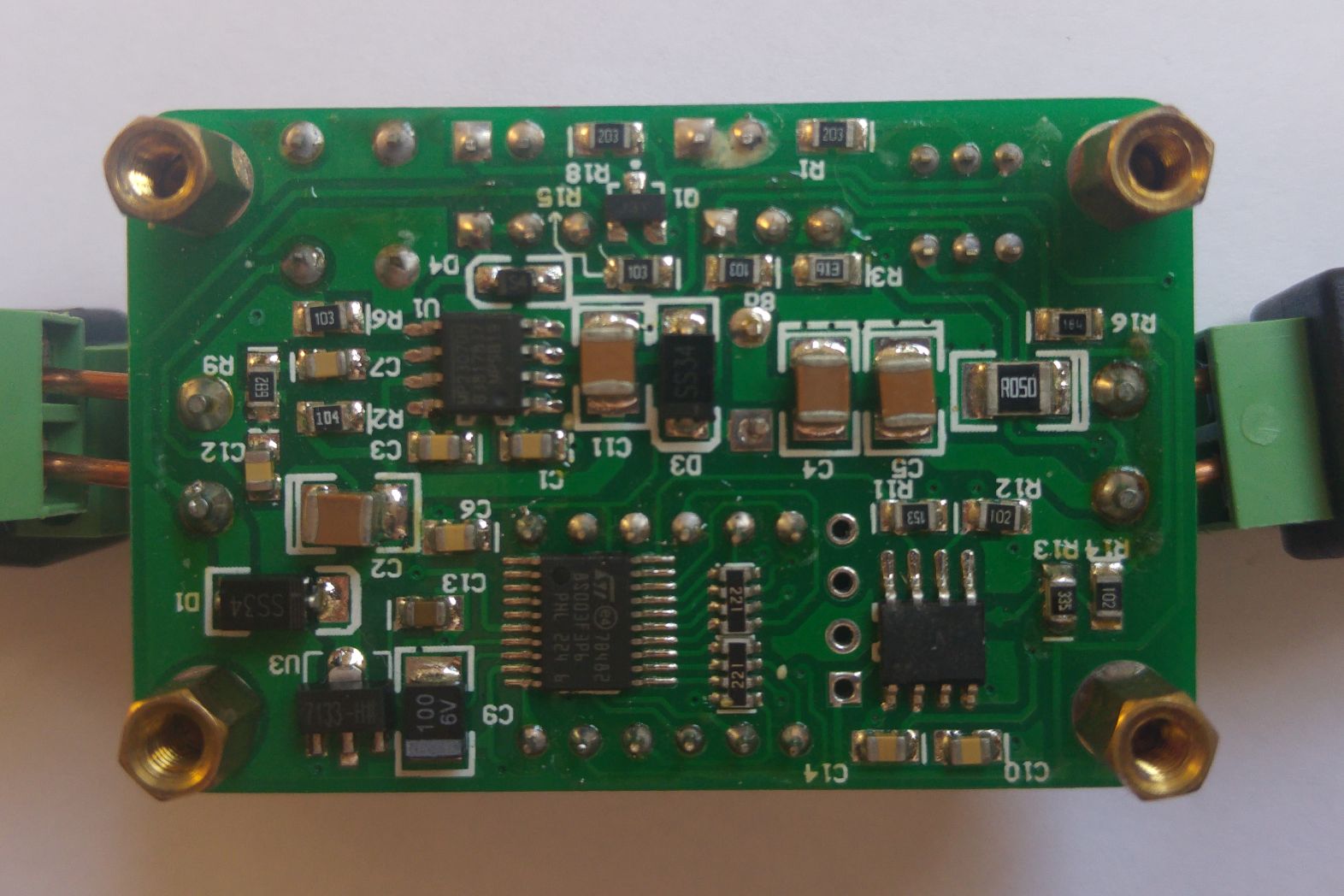
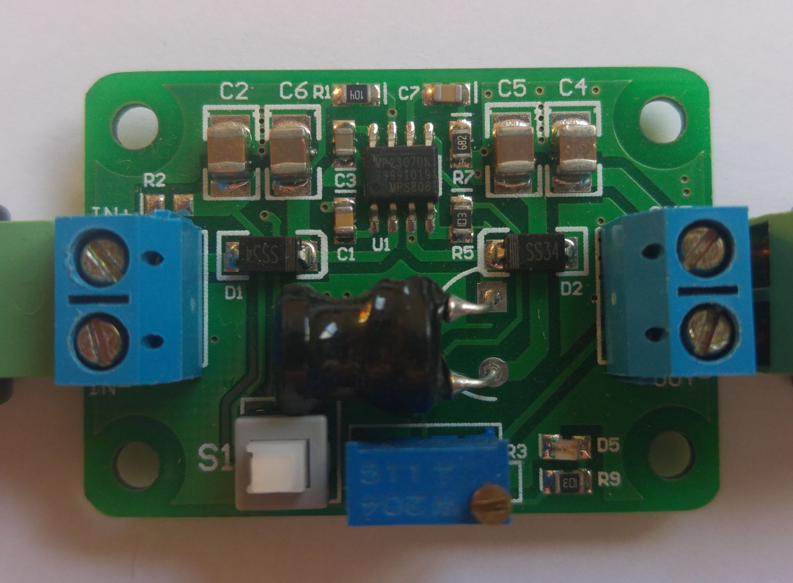
This module was sold on eBay as “DC Step Down Converter 2A Constant Voltage Current w/ Voltmeter Ammeter”. It has adjustable voltage, current and a display that can show input/output voltage and output current. Very nice for prototyping. For some people this can even be an alternative for a proper bench power supply. This module has connectors that are similar to the “Adjustable” module, the method of adjustment is also similar.
Fine
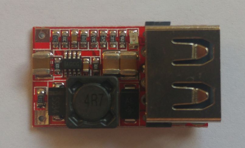

This module by QSKJ was listed as “Fine 6-24V 12V/24V to 5V 3A CAR USB Charger Module DC Buck step down Converter”. It is one of the smallest modules in the test. This is clearly built for integrating into other projects as it features two solder pads for input. The output is a rather nice female USB port. Listing mentions lots of additional features, such as latest USB identification circuit, protection circuits, ultra-low static current (of 0.85mA) and more.
600mA
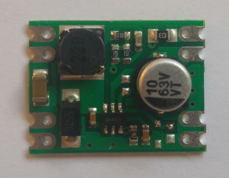
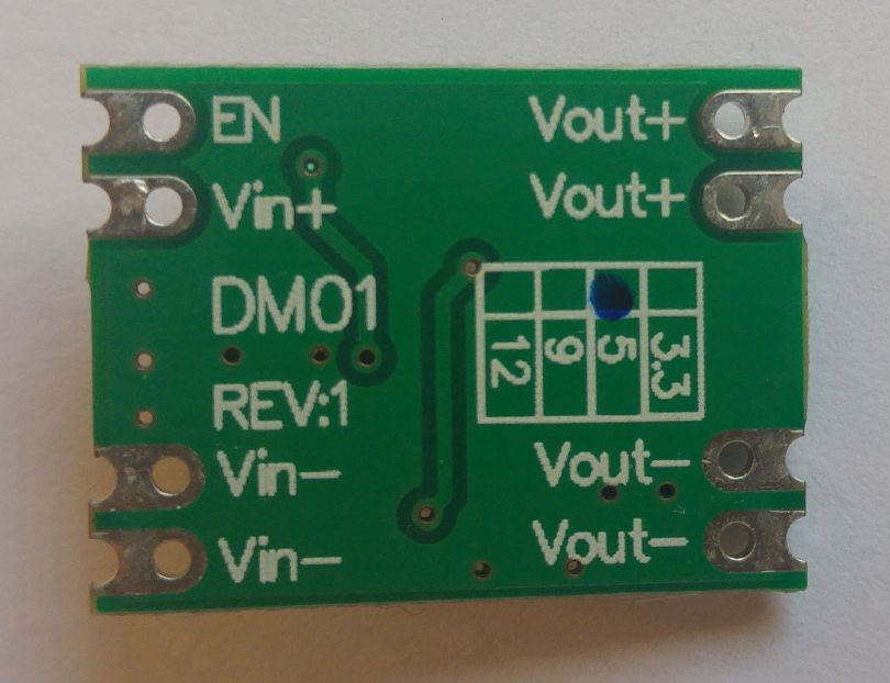
This module marked “DM01” is 100% designed for integration. Inputs and outputs are through solder pads. Seems like this module also comes in 3.3, 9 and 12 volts editions. It was listed for sale as “600mA DC-DC Step Down Buck Module 6-55V to 5V Fixed Output Voltage Regulator”. It could be the smallest module of the 6, but the lack of a USB port makes it an unfair comparison. One feature that differentiates this module from others in the test is that it has an “EN” pad. You can control this connector to shutdown and start the module when needed. Shutdown current is advertised as less than 1uA. If you are just going to bridge this pad to “Vin+”, no worries too, this module’s “no load current” is just 0.7mA.
Precise
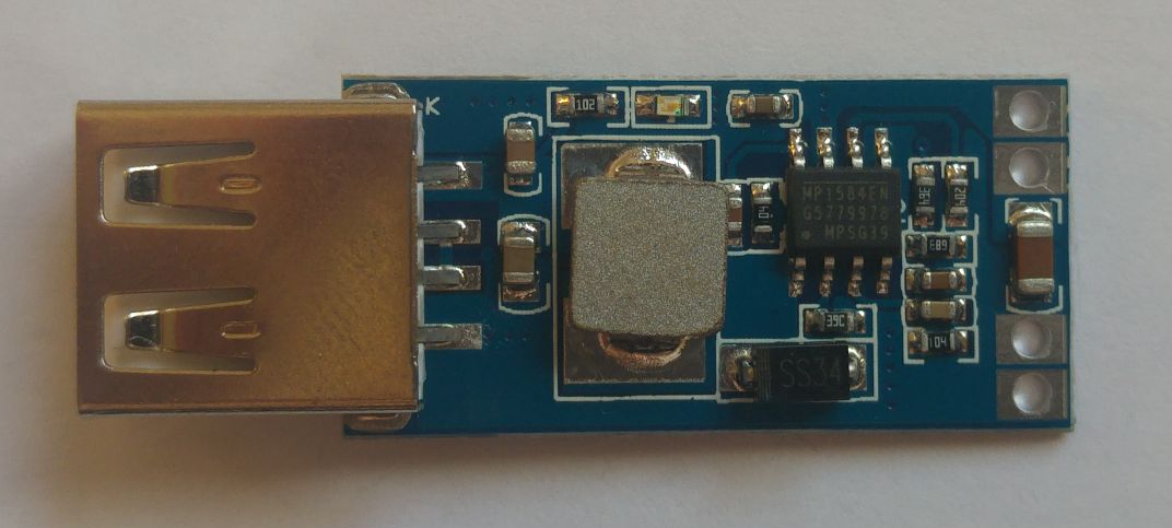

This module has the same connections as “Fine” but it is a bit larger. It was sold as “3A DC-DC 9V/12V/24V to 5V USB Step Down Power Module 2A Precise Vehicle Charger”.
Voltage and current
Here are some electrical properties of the 6 modules. I didn’t have module properties for “Cigar” so the ranges are based on chip specs and could be better than actual module ranges.
| Module | Input voltage | Output voltage | Max output current | Peak output current |
|---|---|---|---|---|
| Cigar | 3 - 40V | 5.4 - 5.5V | 1.5A | ? |
| Adjustable | 4.75 - 24V | 0.93 - 18V | 2.5A | 5A |
| Ammeter | 4.5 - 24V | 0.93 - 20V | 2A | ? |
| Fine | 6 - 24V | 5.1 - 5.2V | 2.1A | 3A |
| 600mA | 6 - 55V | 5V | 0.6A | 1A |
| Precise | 7.5 - 28V | 5V | 2A | 3A |
Peak current refers to ability to provide high current for a limited length of time. Max current refers to maximum current the module can provide consistently. Mind that some modules mention that operating at max current might require an additional heat-sink or cooling solution.
Few points worth mentioning: first, the “Cigar”, with its fixed USB output connector is providing voltage that is too high by proper USB standards. It could be due to old age or just bad quality. The difference is about 10% and I would consider it not usable. Second, most modules are capable of input voltages up to about 25 volts, but few can do 40 volts and higher. Kudos for that.
Switching circuit properties
| Module | Chip | Frequency | Inductor | Stated efficiency |
|---|---|---|---|---|
| Cigar | MC34063A | 100Khz | 220µH ? | 83% at 24V and 500mA |
| Adjustable | MP23070N | 340Khz | 10µH ? | up to 98% |
| Ammeter | MP23070N | 340Khz | 10µH ? | ? |
| Fine | MP2315 (AGCG mark) | 500Khz | 4.7μH | 12V to 5V 1A can up to 94% |
| 600mA | HT7463A (463A mark) | 1250Khz | 22µH | up to 96% |
| Precise | MP1584EN | 500Khz | 15µH ? | up to 96% |
Higher switching frequency will mean less ripple on the output (more accurate voltage/current) but causes more overhead due to switching, which reduces the efficiency a bit.
Some inductor values have a ‘?’ next to them. This means the component was not marked and the value was estimated based on recommendations in the datasheet. Usually a lower frequency will require, a larger, higher value inductor.
Testing
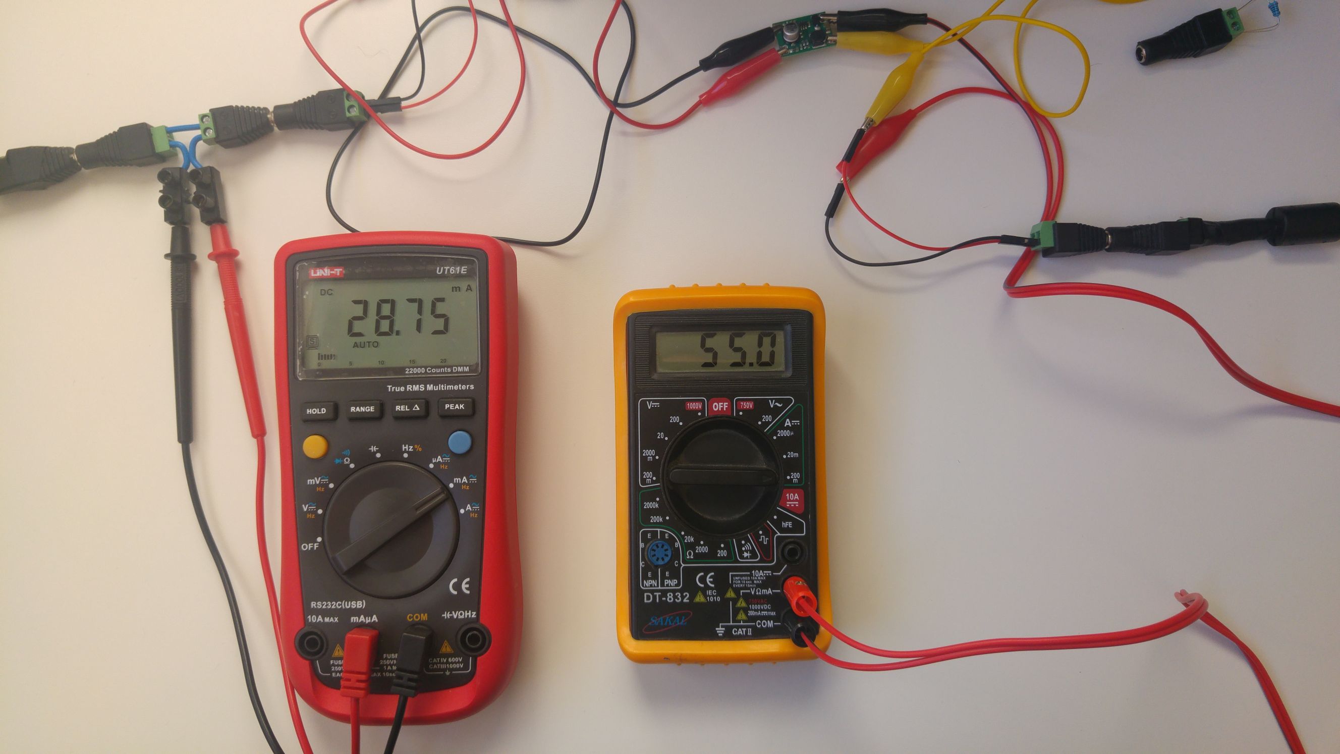
First I measured the current used by my device, on the output side of the converter, which was around 50mA. I then I created a dummy load of 100 ohm using two 200 ohm resistors in parallel. I used a resistor array to reduce the load on each individual resistor which was rated for 0.25W. Due to Ohm’s law, a 100 ohm resistor would cause a 50mA load for a voltage of 5 volts, similar to what the device would.
Next I measured the current used by the converter on the input side, for both a device load and a dummy load. I observed that a real load and a dummy load with same average current both have a similar efficiency. A difference could arise since the dummy load power draw is fixed while the device could draw power in bursts, but this didn’t affect the results significantly. I concluded that using dummy resistors is good enough approximation for this test.
I then made dummy loads for 25mA, 50mA and 100mA currents using 1, 2 and 4 resistors in parallel.

To affect the measurement as little as possible, I used the ammeter on the input side (in series) and calculated the current on the output side using Ohm’s law I=V/R. This way there was no impact on the output side which could add a voltage drop and influence the results. Voltage V was measured in parallel and resistance R is known and depends on the dummy load used for each test.
The power supply for the test was providing 12V, but due to the voltage drop in the ammeter, the input voltage of the modules is a bit lower.
Results
I calculated the efficiency of each module per each type of load as:
eff = Pin/Pout = (Vin*Iin)/(Vout*Iout)
Datasheets of some of the chips used in the modules contained an efficiency graph. The efficiency is a function of voltage and current. When available, I added the listed chip efficiency for the relevant Vin and Iout in the last column. Some modules have efficiency charts that don’t cover low current ranges, which might be an indication for the type of load the chips were (not) designed for.
Output current of 25mA
| Module | In V | Out V | In mA | Efficiency | Chip efficiency |
|---|---|---|---|---|---|
| Cigar | 11.82 | 5.46 | 21 | 60% | |
| Adjustable | 11.63 | 5.08 | 35.65 | 31% | |
| Ammeter | 11.58 | 5.04 | 40.04 | 27% | |
| Fine | 11.91 | 5.12 | 13.7 | 80% | 87% |
| 600mA | 11.9 | 5.04 | 14.2 | 75% | 74% |
| Precise | 11.9 | 4.98 | 14.75 | 71% | 75% |
Output current of 50mA
| Module | In V | Out V | In mA | Efficiency | Chip efficiency |
|---|---|---|---|---|---|
| Cigar | 11.52 | 5.49 | 38.6 | 68% | |
| Adjustable | 11.45 | 5.08 | 47.44 | 48% | |
| Ammeter | 11.39 | 5.05 | 52.2 | 43% | |
| Fine | 11.73 | 5.13 | 26.98 | 83% | 89% |
| 600mA | 11.72 | 5.01 | 26.66 | 80% | 86% |
| Precise | 11.72 | 4.98 | 27.3 | 78% | 77.5% |
Output current of 100mA
| Module | In V | Out V | In mA | Efficiency | Chip efficiency |
|---|---|---|---|---|---|
| Cigar | 11.15 | 5.54 | 76.3 | 72% | |
| Adjustable | 11.22 | 5.08 | 79.8 | 58% | |
| Ammeter | 11.18 | 5.04 | 76.1 | 60% | |
| Fine | 11.41 | 5.12 | 54.6 | 84% | 91% |
| 600mA | 11.46 | 4.9 | 51 | 82% | 88% |
| Precise | 11.38 | 4.96 | 53.5 | 81% | 82% |
Conclusion
Differences can be significant as seen above. At the lowest load test (25mA), the worst performer uses 3 times more power than the best.
Efficiency differences between modules become more subtle as load increases: 2x for 50mA and 1.5x for 100mA.
Input voltages are different. Higher current on the input side means higher voltage drop in the ammeter, resulting in a lower input voltage relative to the output of the power supply.
Listed chip efficiency is within 5-10% of the measured module efficiency. The delta could be due to inefficiencies in the module itself or due to differences in the overall conditions (temperature, etc).
And the winner is: “Fine”! This module is clearly the best for low power scenarios. When reaching currents of 100mA the differences between the 3 leading modules are minimal.
What makes “Fine” better than others? It is a relatively new IC. The datasheet is from 2014 where, for comparison, the MP2307’s is from 2008. It also features a very low Rds(on) values (90mΩ/40mΩ), but most interestingly the MP2315 has AAM (Advanced Asynchronous Modulation) power-save mode for light load.
Advanced Asynchronous Modulation (AAM) is a proprietary technology of MPS. With this technology in place, the IC will reduce its frequency when it detects low loads, thus reducing the overhead of switching but potentially introducing instability and ripples. A resistor’s value on the AAM pin determines when to start this behavior. Feel free to correct me in the comments if I am not explaining this correctly.
In conclusion, if you want an efficient module for light loads, you might want to try this one by QSKJ with an MPS MP2315 chip marked as AGCx (I have seen AGCG or AGCE used specifically). If you have other recommendations, please share them in the comments below. Have a great project!
Thanks!
Thanks so much for this article! I’ve been searching for something like this for a while, since I’ve been testing with these regulators too (broke some in the mean time 😉 )..
I’m using ‘Fine’ for a hobby solar-project, charging my phones etc. What I can’t figure out with my ‘Fine’ is this: My input is 6.5 V/350 mA, this will result in 4.85 V/240 mA after ‘Fine’ is done and having a charging phone connected, so it should draw some juice.. Now, maybe I’m just overseeing some basic physics here.. Do you think I do have a faulty ‘Fine’?
Hi Roedi,
Those numbers don’t sound that good… Perhaps the module is not really able to drive 5V with an 6V input. Are you using a battery between the module and the solar panel? Is the phone close to being fully charged?
I think you should connect a power supply at the input and a dummy load at the output and try different input voltages and currents and see if this has effect on the input. Map how different inputs affect the voltages on the output. Output voltage should be 5V, not 4.85V.
Arek and Roedi. These fine modules are fantastic. Been playing with a lot of solar stuff, also mppt … but the main problem is efficiency! The modules draw power and other stuff making most of them not useful. The fine does … what it’s name does … BUT … you can make it even better because there is an SS34 diode at the input for polarization protection. Well, why would you need that? It’s a schottky diode so you will loose about 0.3V of input voltage and it will also decrease efficiency!
This is a great article. Thanks for putting the work in to make this, it’s very informative.
Hi,
i’m trying to power an arduino pro mini with this adjustable buck converter: https://it.aliexpress.com/item/10PCS-LOT-Mini360-DC-DC-Buck-Converter-Step-Down-Module-4-75V-23V-to-1V-17V/32582509989.html?spm=a2g0y.10010108.1000016.1.7b3c9d20LsRqVF&isOrigTitle=true
The arduino keeps rebooting when the engine RPMs are high. What is the most appropriate module against interferences?
Thanks
Hi Filippo,
How are you powering the motor? Please include a schematic of your circuit. This module is good for 1.8A and 3A peak.
The comparison is not very fair.
1. The output current of 25-100 mA is very low for any phone. Should have used 1-2 Amps.
2. 2 adjustable regulators haven’t been tuned to a single output voltage output, that’s why at these very light loads they have lower efficiency. This is a result of being much more universal devices.
The 1st UUT had too high voltage, which is most likely because it was supposed wi work with much highter loads. Thus, it’s not good of driving mAmps loads, but would probably be OK with 1-2 Amps.
Having said all of that I think MP2315 would still be the winner.
Hi Maxim,
I general you are right, but this article is titled “Efficient conversion for low-power electronics” not “… for phones”. I believe it is fair to perform a comparison for the 50mA range, nothing wrong with that.
Naturally converters aimed at 1-2A loads perform worse in this scenario, which is exactly what I was trying to show.
Somebody looking to power a device in the 50mA range should now know to be wary of generic phone chargers. 😉
Nice overview, thanks.
I measured output ripple in 4 different DC-DC buck step-down converters, which could be alarming high (in the order of magnitude of 700mV; 300 mV output ripple seems to be a “low” value). The output ripple usually increased with input voltage and current drawn.
E.g., in an LM2596-based adjustable DC-DC converter, it was “forgotten” to install a capacitor between the output and sense-input (thereby multiplying the output ripple with a factor related to the difference between output voltage and sense-voltage of 1.23V(Cff in LM2596 datasheet: https://www.onsemi.com/pub/Collateral/LM2596-D.PDF). However, adding a 15nF capacitor did not solve all of the ripple (I would consider a ripple up to 100mV acceptable).
Did you / could you measure output ripple and/or could you replicate my measurements?
BTW. in my hands “Fine” didn’t have any ripple at all (< 30 mV up to 900 mA, did not yet test higher currents). I will look into it again to be sure it was a decent measurement. For Fine the minimal input voltage was 6.4V (to obtain an output of 5.1V).
Ps. Ripple measured with a Tektronix oscilloscope, maybe it is also possible to measure it with a multimeter set to AC Volts.
Hi Cat,
Thanks for sharing your test results and observations.
I was not concerned with the ripple as in my scenario the output of the buck goes to a linear regulator.
I think that if you are sensitive to ripple you should look for a buck with a fast switching frequency. I believe the higher the frequency the smaller the ripple.
Note that “fine” has a switching frequency of 500Khz while LM2596 is probably just 150Khz.
Is there any reason not to use a LD1117AG50 or variant? It is compact, temperature, voltage and current stabilised and give a good reference voltage regardless of input (within limits) provides 1A and is cheap as chips (cheaper in fact). I use the all the time and managed to get 50 (in a tape) for £1.22! They also do different form factors and output voltages (i also use the 5V version).
Hi Bob,
The main reason why not to use it is that it is a voltage regulator and not a buck converter. The difference is explained in the article. In this scenario, this chip would have an efficiency of ~40%. In a high current scenario, this chip will overheat.
Hi, thanks for this!
I have a 12v motorcycle power source and want to power 5v into a sensor. A nice and steady 5v is important for accurate readings. Bonus points is for not using too many amps, as the stator can only pump out so many amps.
Do you have any advice on how to convert a 12v source (which may itself not be super steady, I have no idea) into a steady 5v?
Thanks!! I’m so lost.
Hi Kyle,
Are you going to use this only when the engine is running or also from battery when the engine is idle?
There are several ways to do this. To be able to choose the right way you need to specify how many amps the load (sensor?) you are putting on 5V will be using. What exactly are you going to connect to the 5V line?
Hey, thanks for the reply! I’ll only use it when the engine is running.
thanks for the excellent overview 🙂
Hello, and thanks for the article! I am looking for an efficient converter for my led christmas lights. I have a solar panel to charge a 12V battery, but need 5V @ 175ma to power the leds. Do you think the “fine” would be the best choice, or do you have another suggestion? Thanks again!
Hi Bill,
Do your lights include a led driver? LEDs typically need a constant current source. None of the converters above are constant current.
If your lights are combined with a driver and have a USB plug, then yes, the “Fine” should do the work of converting 12V from the battery to a USB 5V source.
Yes, the string of lights has a USB plug with a controller inside to set different modes, brightness, and a timer. Last year I powered them from a power bank that I recharged every day and put back outside at night. I didn’t want to worry with that this year.
I need to test 6 volt starter solenoid windings on a 1950 era automobile. The spec is: both windings @5v (80F) 85-90 amps, hold–in winding @5v (80F) 14-16 amps. Not sure where to start, I have a 6 volt automotive battery. Thanks
Hi Dan, I am not sure I know how to help you. Perhaps test the resistance of the solenoid and compare it to the expected value using your data and the V=IR formula.
Nice article thanks for all the work done here !
Can you give us the reference of Fine ? I can’t find it on AliExpress for example.
I have an Arduino mega that will manage with relay a 12v alimentation with relay for LED light and I want to dedicate this electricity to the Arduino to avoid to add an charger.
Thanks for your answer.
Hi Blop,
Here is a link to the item on ebay:
https://www.ebay.com/itm/Fine-6-24V-12V-24V-to-5V-3A-CAR-USB-Charger-Module-DC-Buck-step-down-Converter/401183759010
I am sure you can find this from other sellers and sites if you look for this title and pics.
Great work
Hi,
I’m looking for a DC DC 12V to 5V that can provide at least 2A on 5V.
I ordered one that stated to be able to provide 3A @ 5V but after measuring it only provides +- 0.28A which is insufficient.
Do you happen to know such a converter?
It’s to charge a cell phone quickly (to provide enough power for GPS, full screen brightness) and the phone still charging.
Thanks in advance!
Thomas
Hi Thomas,
What you are trying to do is more complex than what it seems at first.
Your adapter can probably provide 3A as stated, it is just that the phone doesn’t draw as much as you want. The reason is that phones use various charging protocols to discover the max current of the charger. By default the current an USB charger provides is 500mA.
You probably need something smarter as your charger and there are products that will do it.
Some additional things for you to consider:
Is that 0.28A on the 12V side of the converter or on the 5V side?
Did you try to put a controllable load on the converter output and test it at 1A, 2A and 3A?
What charging protocols your phone supports?
Good luck
Hi
I need 600mA converter DM01 bill of material. I would appreciate any kind of help.
thanks
Thank you! I’m buying the “FINE” to replace a mechanical regulator for my fuel gauge. 🙂
Thanks for putting the effort. I got my doubts answered in your description.
Thank you for your research. I have purchased one of the Fine converters and it works a treat for my application which is a dummy battery to supply a Huawei e5577 pocket modem.
Now I can run it constantly in my car. The load is so minimal that it doesn’t worry me.
Which product placed in second place?
I already have a cable to solder onto the Vout.