
This article covers an automotive project, in which I connect unused buttons on my car’s steering wheel to a micro-controller, which in turn emulates a keyboard and mouse device to the car’s infotainment system via USB.
tl;dr, the buttons form a resistor ladder and I use an STM32 black pill board to read the state of the buttons using an ADC. The STM32 emulates keyboard, consumer and a digitizer USB HID devices that allow to send pre-configured actions as if a person is making them. PlatformIO IDE and Arduino framework are used to write the firmware.
Introduction
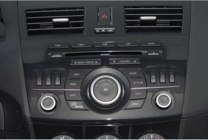
I drive a Mazda 3 2010, 2nd -gen vehicle. As you would expect from a 2010 model, it came with a boring, non-touch, old style car stereo. Last year I replaced this stock head unit with a new Android-based one. This turned out to be one of the best purchases I have ever made. The new device runs Android 9, comes with Wi-Fi, Bluetooth, GPS, USB, front and back camera connections and many other features. I can install Play store apps on it and enjoy connected services. This upgrade truly improved the driving experience.
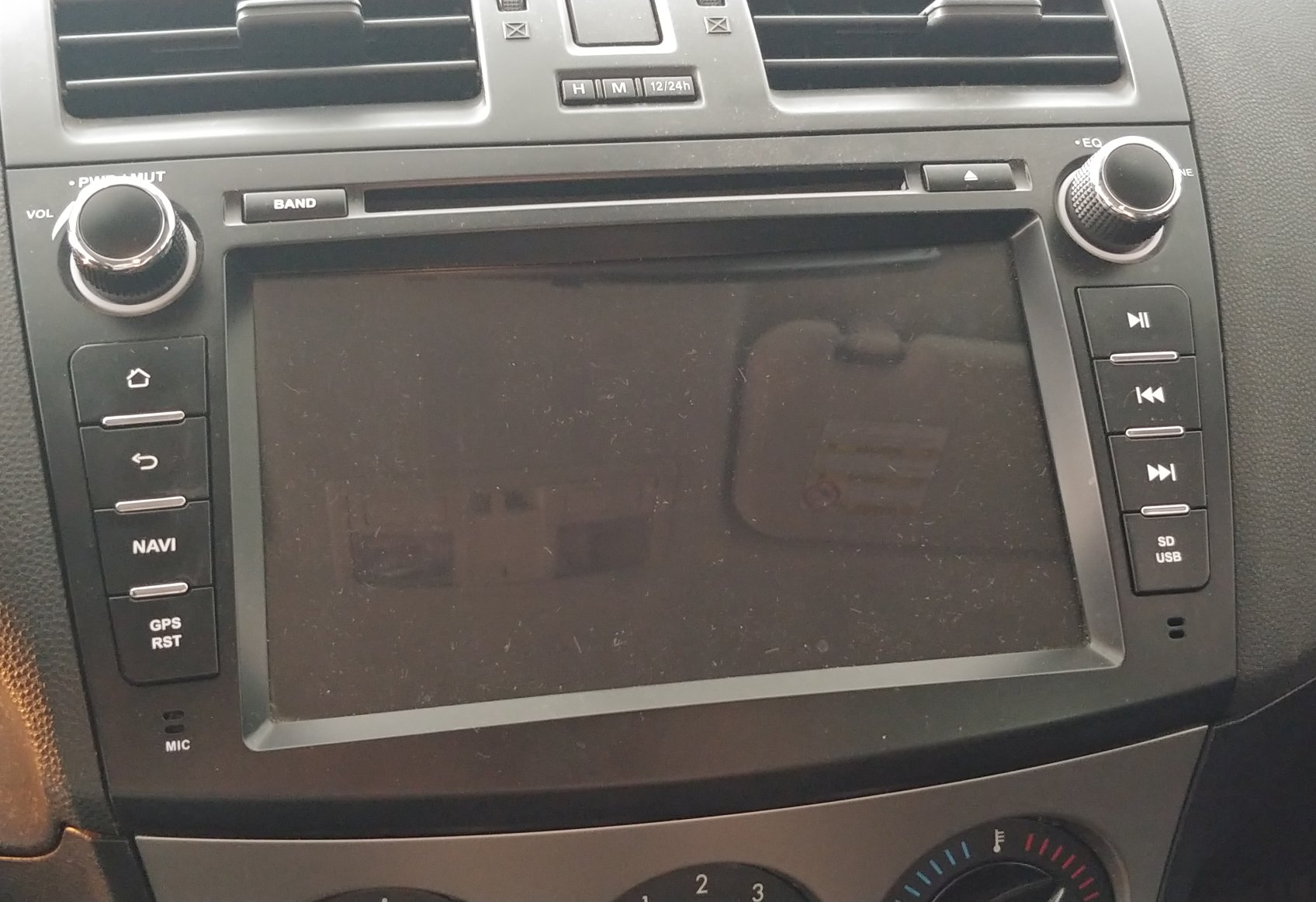
The head unit is meant to be controlled via media buttons on the steering wheel and also integrates with the original media LCD display. The display is separate from the head unit and is mounted at the top of the dashboard. This display shows the current radio station, volume, etc. To achieve this integration the head unit comes with a CAN bus interfacing box.
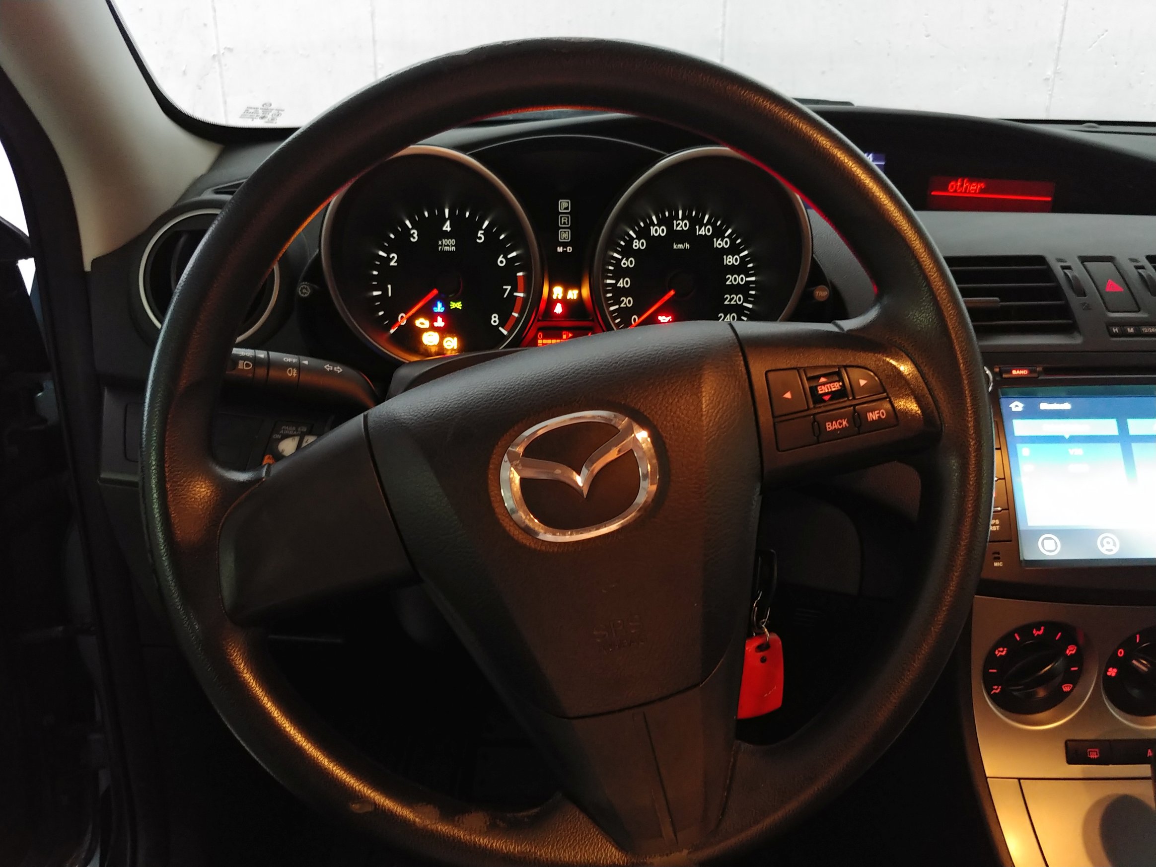
Mazda sold several levels of Mazda 3 2010 vehicles in my region. The basic version has a steering wheel with one set of buttons for the “multi information display”, which is yet another LCD display that shows data such as fuel consumption. The more advanced Mazda 3 versions come with a steering wheel that has 3 sets of buttons, fancier leather, etc. The two additional sets of buttons are media buttons and cruise control buttons.
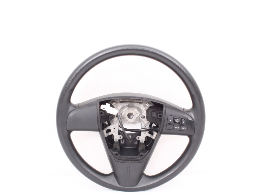
After upgrading the head unit, I was in a situation where I knew it supports control via media buttons but I didn’t have any on my steering wheel. My intuition told me that controlling the head unit from the steering wheel is clearly safer than by using the buttons on the head unit itself, so I decided to upgrade the steering wheel.
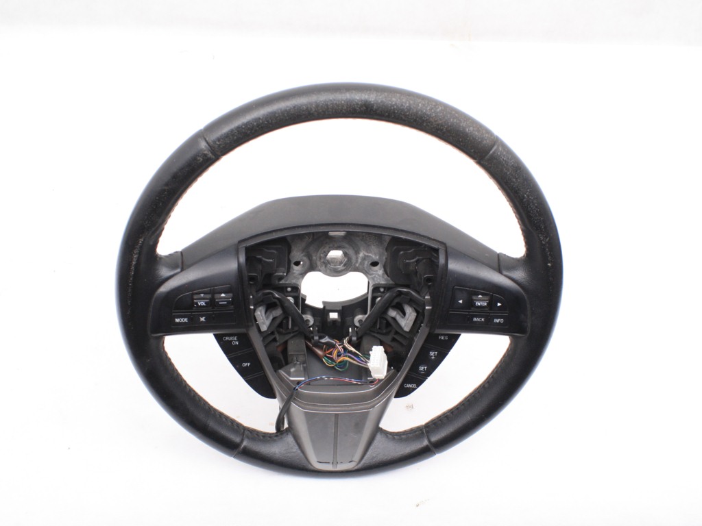
I did some research and discovered that the different types of steering wheels are compatible and that all the connectors are the same. This makes a lot of sense in terms of having the wire harnesses and connectors standardized. I bought a used steering wheel from a more advanced 2nd-gen Mazda 3 that was totaled and got it installed in my car.
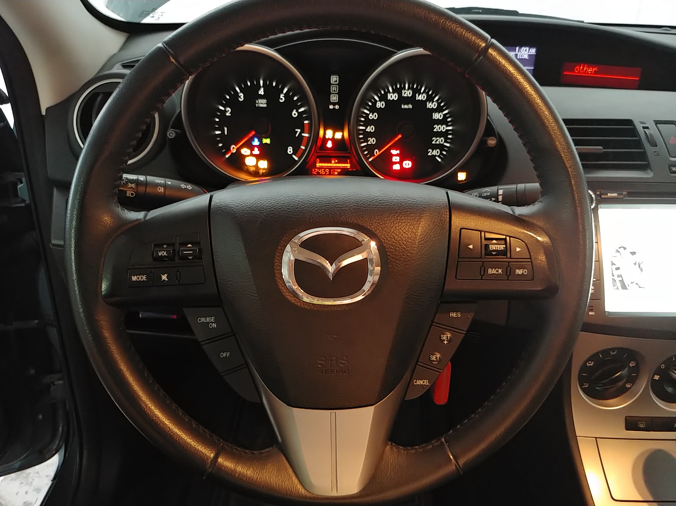
As expected, media buttons now worked and the “multi information display” buttons were also fine just as before, however, I now had cruise control buttons that did nothing. They didn’t allow the native cruise control functionality and they also didn’t register in any way in the in-car entertainment system. Looking at the documentation (mainly the workshop manual available online) and by testing the connector with a multi-meter, it is clear that each set of buttons is separate, has its own wires and goes to a different component in the car.
There are some mentions online that enabling cruise control for a model that didn’t come with one requires programming of the Engine Control Unit (ECU). I didn’t want to go as far as changing anything in the engine or the ECU, plus, I didn’t really need cruise control. What I thought would be awesome though, is if I could use these buttons for generic uses with my new head unit. To do that I will need to get the “clicks”, process them and pass them to the head unit somehow.
So let’s start. 😉
Getting access to the buttons
I preferred to make as little changes to the car as possible. The first method I tried, simply because it is minimally invasive, is by listening to the CAN bus.
The vehicle has two CAN buses available in the OBD2 connector; a high speed 500Kbs bus and a low speed 125Kbs bus. I used an ELM327 off-the-shelf Bluetooth module, as well as an Arduino with a MCP2515 CAN Bus Module to tap to the buses. The Arduino runs a script based on arduino-can-reader that forwards the messages to a PC via a serial connection, where a python script based on python-can-monitor renders the messages on the screen in a nice way.
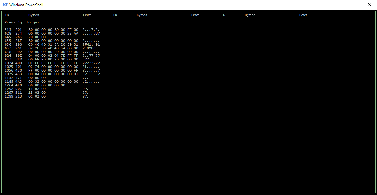
I was able to read data, such as communication between the head unit and the media LCD display. Try to find which radio station I am listening to in the screen shot above ;). However, there is nothing related to clicks on the cruise control buttons or media buttons. Looking at results of Mazda CAN bus mappings done by others online (1, 2, 3, 4, 5, 6), I reached the same conclusion that these sets of buttons report directly to related “clients” without using the CAN bus.
Reading through the workshop manual for the vehicle, I was able to find some information about how cruise control buttons work. It is actually very well documented! The buttons form a resistor ladder (kind of) that goes through a clock spring (which is the device that allows the electrical connections to go through a rotating steering wheel) and then directly to the PCM (power-train control module) AKA ECU. The PCM has a pull-up on one of the connections, which combined with the resistance of the buttons forms a voltage divider so the PCM can calculate if buttons are pressed.
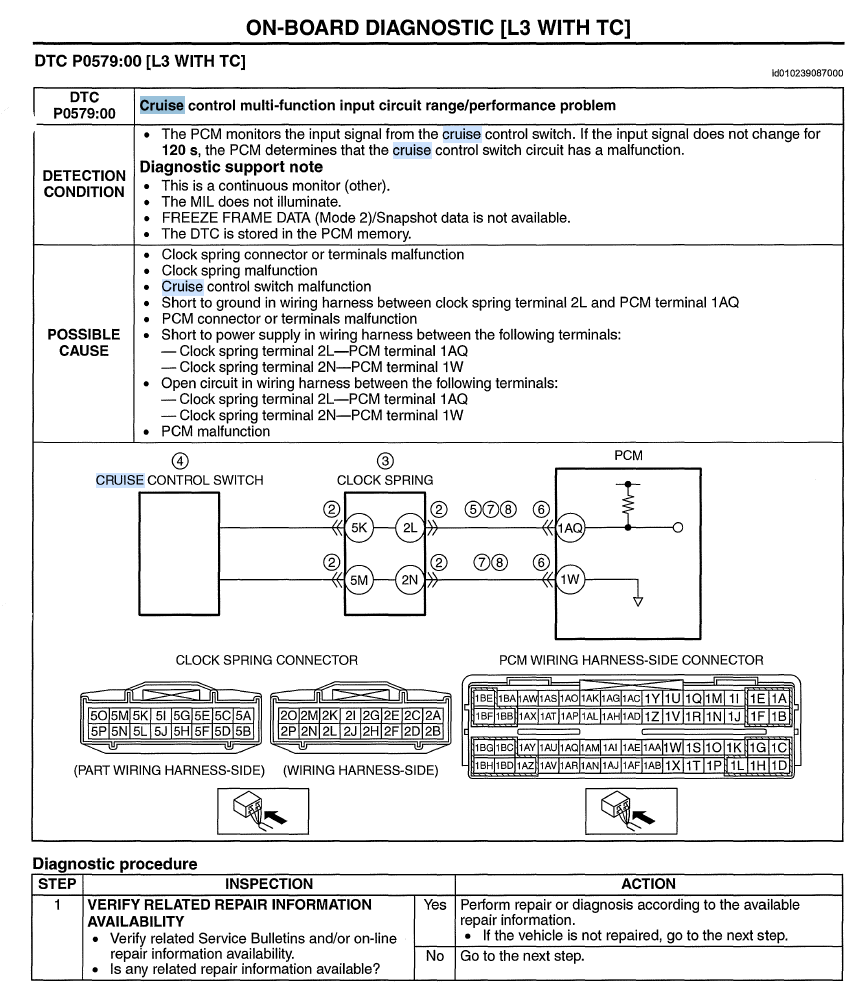

This meant I needed to get access to the two wires and tap into them. The schematic shows which positions in the connector are the right ones. Obviously, we want to tap between the clock spring and the ECU and not in the part that rotates. Taking apart the steering wheel column is pretty easy. Once I gained access inside, I was able to measure voltage and resistance and confirm that I have the right wires. I found something that dictated the way forward. The system is implemented in such a way that the wires are pulled up only when the key is in the ON position (pre-start or when the engine is running) and it is not pulled up in the ACC (accessory) position when the radio is working but the engine is not. In retrospect it makes sense because why would you need cruise controls when the engine is not running? This did require me to cut and re-route the wires instead of merely “tapping” them because I was interested in reading the buttons in both the ON and ACC modes. Not a big deal, I would just pull up myself later in the next sections. Should also simplify the integration as I would not have to deal with any influence of the ECU, different levels of grounds, etc.
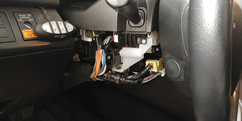
Before 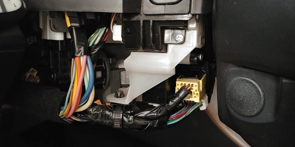
Close up 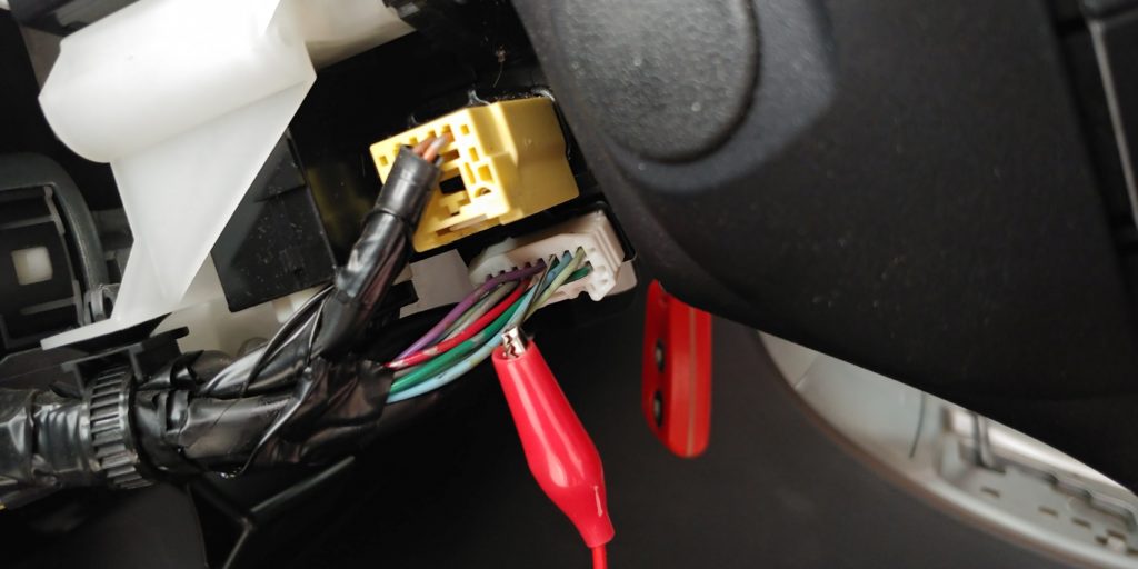
Testing 
New wires connected
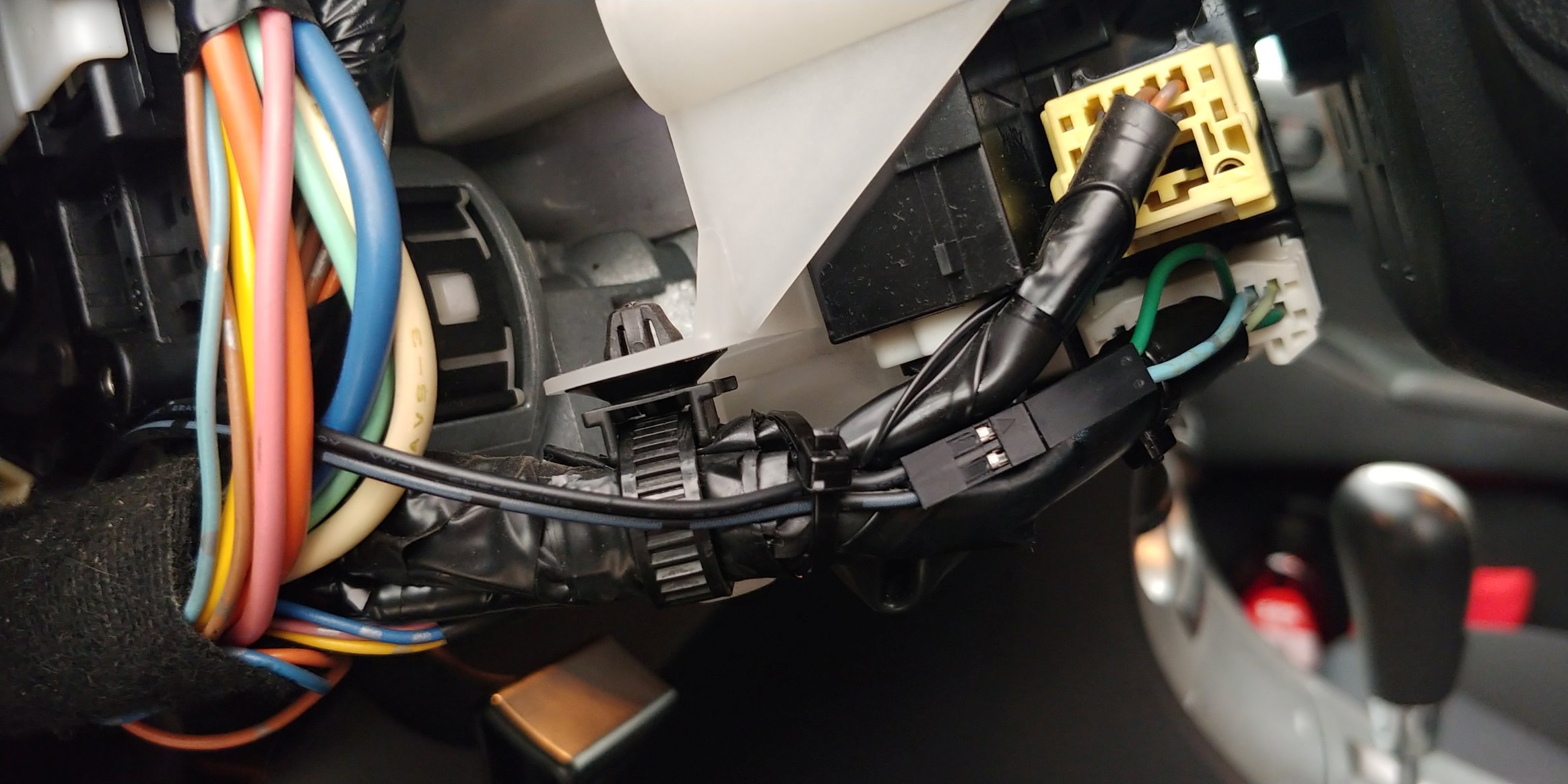
Now that the ECU is disconnected from the buttons, you may wonder if that is an issue, but that was actually the situation before the steering wheel was upgraded. Open circuit and short circuit on this pair of wires are “not defined” and “cruise off” respectively. By design this facilitates safety. You wouldn’t want the cruise control to go crazy on you while you are on the road. Again, it doesn’t matter much because this function is not enabled in the ECU of this car anyway, but in theory we have yet another layer of security in case of a malfunction.
Now I have a long pair of wires that I can route to another place in the vehicle where I can sample the state of the buttons. The wires are data wires and not going to carry any significant current, so no need for any special connections or other power related considerations. Now that I have access to the cruise control buttons, how am I going to use it?
Controlling the head unit
The Android by itself has no “gpio” pins or an ADC that I am aware of and that I could use to read the state of the buttons. So I needed to add some kind of a micro-controller in the middle that would interface between the hardware buttons and the Android head unit. How can I pass click events to the Android?
My first attempt was to emulate a Bluetooth keyboard with an ESP32. This turned out to be rather simple. I followed this example project that uses the ESP32-BLE-Keyboard library. Unfortunately, the head unit can’t be connected to other Bluetooth devices as it is a Bluetooth device itself. The head unit normally connects to a driver’s phone to function as a headset and audio device. So we have a client to client situation.
Next, I considered forming a Wi-Fi connection between the ESP32 and the head unit and sending click events from the ESP32 to the unit over Wi-Fi. To respond to the events I would either need a specialized Android app on the unit or using something like MacroDroid. Though I have experience with writing Android apps, I decided this is too complex for the scope of this project.
In the end, the device making the integration would have to be powered somehow, most likely by a USB connection. If we are going to take up a USB socket anyway, we might as well use the protocol and not just the power. The winning solution was thus emulating a USB HID (human interface device) with a micro controller. This has several advantages: first, it is fully wired and thus more secure and reliable than a wireless connection. Second, with a HID it is easy to emulate a keyboard, as well as other types of HID devices such as mouse, digitizer (kind of like an absolute coordinates mouse) a “consumer” device, etc. A consumer device is a special class of an USB HID device that can invoke certain predefined actions such as “Home”, “Stop”, “Print”, “Find”, etc. This is actually important because it could often be the easiest or only way to invoke a specific function.
As a side note, I also considered using the USB serial profile, where the micro would send commands to the Android via a serial connection over USB. This solution also requires an app or a service to run in the head unit and seemed too complex and limited to me. Perhaps making a MacroDroid or Tasker plugin for serial communication could be a way to implement it. Maybe using something off-the-shelf like Tasker’s AutoArduino would do the trick?! In the end, though, you will be limited by the actions the automation app is able to execute, so this approach is not as flexible as USB HID.
Since the ESP32 doesn’t have a native USB functionality, I needed a different micro-controller and board for this project. The Arduino framework has a USB keyboard and mouse functionality for certain Arduino boards, such as Leonardo, Esplora, Zero, Due and MKR Family. However, it doesn’t implement a consumer device and the mouse is relative rather than absolute, which is quite counter-productive for executing macros. So we will need a library anyway. One that seemed promising was the NicoHood HID library.
With the COVID-19 outbreak, shipments from the far east are really slow and unreliable. So I looked for something that I already had that I could use to implement USB HID. I found an unused STM32F103 “black pill” board lying around that has native USB and decided that I would use it for this project.
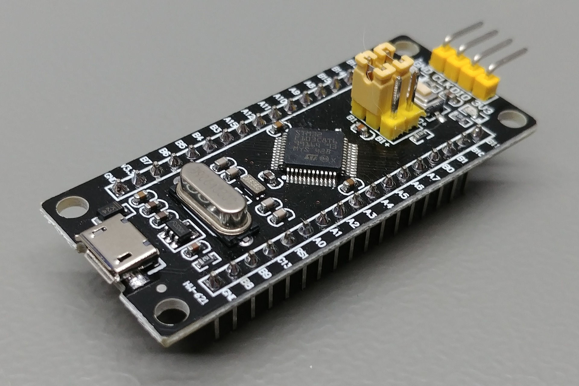
The black pill is a cheap development board with an STM32 micro-controller. If you are going to use it with the Arduino framework, you should be aware that there are two popular STM32 cores. One that has longer history and is based on libmaple by LeafLabs is “Arduino STM32” by Roger Clark. Define “board_build.core = maple” in platformio.ini to use it. The second is more recent, but is an official STM one called “STM32duino“. Define “board_build.core = stm32duino” in platformio.ini to use it. There is a good review of some STM32 basics that you can read if you are going to deal with this architecture.
Once on the STM32, I found two USB HID libraries that seemed relevant. The first is MediaKeyboard by onetransistor and the second one is USBComposite_stm32f1 by arpruss. I chose the USB Composite library that seemed to have more features. It works specifically with Roger’s core. It supports a ton of USB types; HID, MIDI, storage, serial, controllers and in the HID category it can do keyboard, mice, consumer, joystick and more. I tried the absolute mouse device and though it worked OK on a PC, it didn’t work well on Android. After some research, and with the magic of open source, I added a profile for a digitizer device. Now I was able to send touches, key clicks and consumer events to the Android. This gives the most flexibility as I can automate anything that I can input with my fingers. The only downside is that there is no feedback, meaning the micro doesn’t see the screen or get the state. So it is as if you are operating the head unit with your eyes shut.
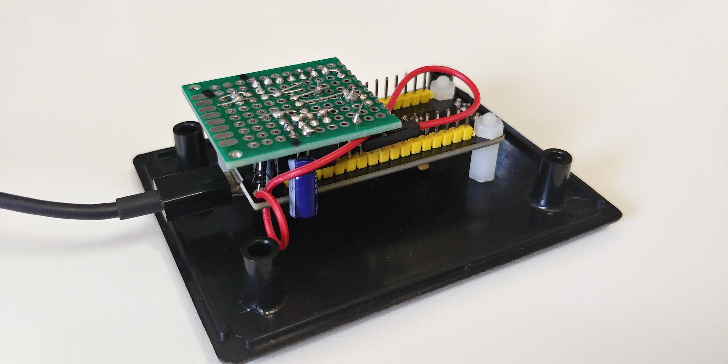
Making the device
The end goal was to wire the development board to a piece of perforated board, put all that goodness in a plastic enclosure, wire it to the buttons and a USB port and put it somewhere in a car. Let’s call this whole setup “the device”.
The first step in making the device was to build the circuit on a breadboard in the lab. I made a small resistor ladder using a few buttons and resistors to emulate the buttons in the car. The resistance on the buttons in the steering wheel was between 0 and 4.3Kohm. To form a voltage divider and utilize the range of the ADC in an optimal way, I decided to use a pull up resistor of 4.7Kohm. The internal pull-up value of the STM32 is about 40Kohm, which would reduce the effective voltage range that this setup will generate. The internal pull-up is also not as stable as an external one. Therefore one section on the perf board would be an external pull up.
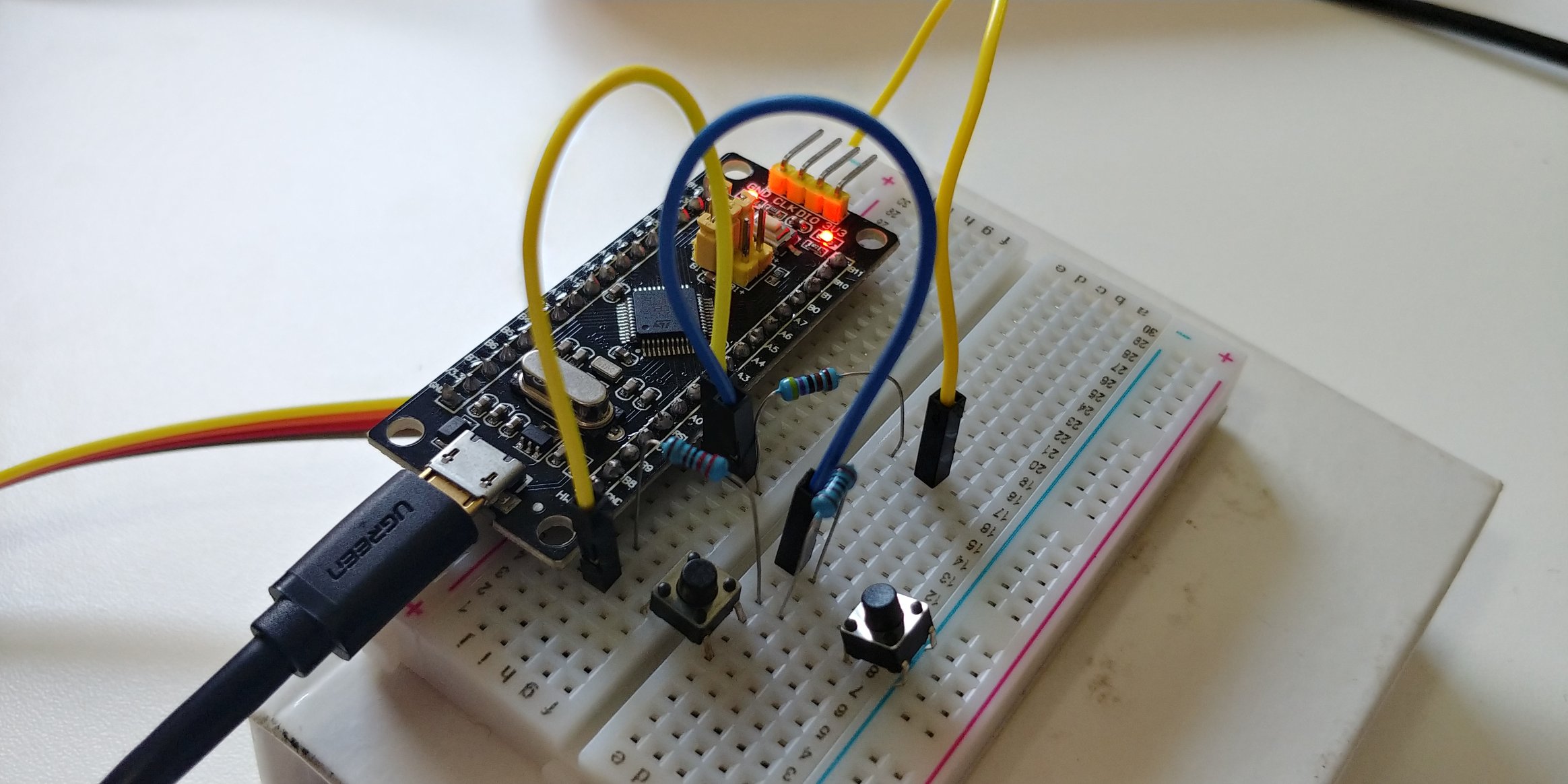
A challenge in this project was getting a clean reading from black pill’s ADC. I was getting outlier readings often that seemed like button clicks when nothing was pressed. The power rails were not very stable. Other components would affect the ADC readings by generating noise. Few things cause that:
- There is just a few uF of capacitance on the 5V and 3.3V rails (other boards would normally have 10-100uF values) – so easy to get unstable power.
- There is no pin for the 5V line – so no natural way to connect power-hungry components such as motors or buzzers.
- There is only one regulator for 3.3V rail – so all users can interfere with one another.
- The ADC reference is on the same rail as everything else – so any drops on the main rail will affect ADC readings.
I guess all these issues are a result of a strict cost target. After all. this board is about $3 delivered. To reconcile some of these issues I made the following changes:
- Added a 10uF capacitor on the 5V rail (this is the max per USB spec)
- Added a 47uF capacitor on the 3.3V rail
- Soldered a wire to access 5V rail directly
- Added a averaging filter in software
- Implemented logic in software to wait for the state to stabilize before button events are generated
Another functionality that I wanted to have is audio feedback. I wanted the device to beep, and preferably beep differently for different types of presses (short, long, double, etc). Therefore another section on the perf board would carry the transistor, resistors and buzzer needed to make simple beeps. Software-wise there was not much to do as the core already had a working implementation of the tone function.
This entire circuit is implemented on a perf board, which has headers to plug the dev board in. As it is a USB HID project, I dedicated the USB port to that function and used a ST-Link dongle to program and debug the device and also used a serial USB adapter to monitor the debug stream. A simple logic analyzer was used to troubleshoot power rail issues and buzzer electrical noise.

The firmware for this project is on github, feel free to fork. The code was written using the PlatformIO IDE. It is not especially complex. Perhaps the most convoluted part is the state logic for handling button clicks. I only implemented the detection of single button clicks at a time (i.e. no combinations), though I think more than one button can be detected with a stable enough ADC. I implemented short and long clicks, which gave me 12 different actions. The actions are hard-coded in the code. Some are simple such as “Home”, while others are complete flows, i.e. to open a “compose new email” screen and pre-fill some fields. I don’t plan on changing the actions often and I didn’t feel it would be a good ROI to implement a generic system where the actions could be programmed to the device separately from the code.
I ended up by mounting the device in a plastic enclosure and shoving it in the far end of the glove compartment.
And now! Demo time:
Got any ideas for improvement? Making a similar project yourself? Share your feedback in a comment.
What is the android unit you bought? Any links?
Hey sea mike,
This one is a EONON GA9363 model. But there are various types by different companies that fit various vehicles.
See https://forum.xda-developers.com/wiki/Hui_Fei_Type for more information.
You’ve just inspired to visit Mr. Eonon and grab a new head unit for my Mazda 3 MPS. Its 2010, with the newer steering wheel. Did you get the DAB USB adaptor? It seems very overpriced.
I had no idea there was a hacking scene at Hui_Fei_Type, so thanks a million for pointing that out!
Hackaday pointed me here, btw.
Hey Mel,
That is cool.
I am not a user of DAB. Not even sure what will happen if you plug such an adapter to the unit. Might not be supported.
I mostly listen to regular radio and stream audio from my phone. You can also stream whatever you want from the internet so lots of options if you aren’t sure about DAB.
Thanks for sharing!
I have managed to install a 2nd gen IS250 steering wheel into my Aristo aka 2nd gen GS300.
The paddle shifter and cruise work but I woukf like to use the steering wheel controls for head unit and phone from the IS Steering wheel.
I am running an Android deck. It needs only two wires to feed the volume mode and tuning functions.
It seems that the input to the deck uses a different voltage for each function. This seems to be dine by using a circuit board known as a resistor ladder. So each switch gives a different resistance when pressed.
I am assuming that one of the deck s 2 SWC wires is an output voltage and when a switch is pressed, a voltage based on the resistance for that switch, sends a particular voltage to the second deck SWC wire.
I would like to see the wiring diagram for an IS250 with SWC for phone and deck.
If I am wrong in my understanding i would be happy to be corrected.
The Android deck has a learn function for each button so it seems to make sense.
There is a pIc of the audio control part of the SWC. I am trying to do this without canbus or axess or pac as they seem unecessary due to the Android deck learning in the set up.
Hey Ludwig,
I believe you are correct in your observations.
It is very common for such sets of buttons to use a resistor ladder.
Just connect the two wires from the steering wheel to the relevant two wires of the head unit.
The head unit puts a voltage across these two and measures the voltage drop that happens on the wire.
You can further test this if you have more tools.
1 – use DMM in resistance measurement mode across the wires of the steering wheel to see if the resistance changes as you press various buttons.
2 – use few different resistor options across the wires of the head unit button control wires. See if that make a difference in the “learning function” of the head unit.
Good luck.
God damn man. You went way further than you needed to trying to find the signal for the cruise buttons in the can system. All you have to do is look at the wiring diagram for cruise control and see if there are analog outputs coming down the column or if it’s just a data bus coming down from the column. I applaud your level of skill though.
Hey John, thanks.
My assumption was that even though there are analog outputs in the column the data might also be processed by some control module and send on the bus. However it turned out that it is not the case. The analog data goes straight to the user of that data (ECM) and it not available otherwise on the bus. So I had to go the more invasive way and cut the analog wires.
Hey there! I am doing something kinda similar for a Android Head Unit and a golfcart + particle.io MCU. What I found interesting is the serial data option. I will be writing my own UI launcher to read data from the MCU into Android. My question is this. You mentioned a USB Serial profile. Do these head units support USB-TTL serial cables? Is this what you meant by “serial profile”.
My MCU is reading CAN / UART data from my motor controllers, bms and a few other devices. I COULD do bluetooth but I would prefer to use a serial connection for the same connectivity reasons you mention. Thanks for the post!
Hey Riley,
Sounds like a cool project.
Yes. The unit I have supports USB to serial adapters. Specifically I successfully tried with a CP2xxx based adapter.
Before you go to implement this in your own app, plug an adapter in the HU and use an existing app to test it. See these resources:
https://play.google.com/store/apps/details?id=de.kai_morich.serial_usb_terminal&hl=en
https://github.com/kai-morich/SimpleUsbTerminal
hey man thanks!
I was not sure about the roms shipping serial drivers. I ordered a new head unit and it will be here this weekend. Ironically, you are the only source of information I have found that was talking about serial adapters and head units 🙂
Sounds great. Let us know if it works or not.
Frankly, USB CDC is pretty much the same thing for all the adapters. So not sure why it is an issue in Windows (for example) to make a universal driver. When I think of it, maybe Windows 10 has a Universal one now. It used to be you needed drivers for different adapter chip-sets.
That’s awesome! I’d like to do this with the phone buttons on the steering wheel rather than the cruise control buttons , as they don’t work when using this headunit. Hopefully I can find something simpler ha!