This is a follow up article to the detailed review of the MLT-BT05 BLE module. In that previous post I mentioned that I got some MLT-BT05 modules with their STATE pin floating. No working STATE pin was an issue for me and I decided to investigate the cause.
Update: same issue was observed with Bolutek CC41 modules that are delivered lately. The conclusion is that this is an assembly or a breakout-board issue and not specific to any type of daughter-board used. Could even happen with original HM-10 modules if soldered poorly to the breakout. Keep reading for a fix regardless of firmware/module.
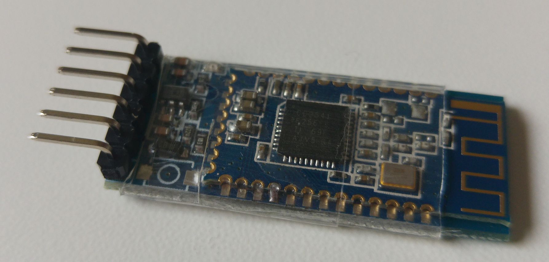
The breakout board has a physical STATE pin and the main chip and daughter board are the same as in other modules with a working STATE pin. The only difference I could notice was the number of solder joints between the breakout and daughter boards. I suspected that this is the cause of the issue and that the pin on the breakout board is simply not connected to the chip.
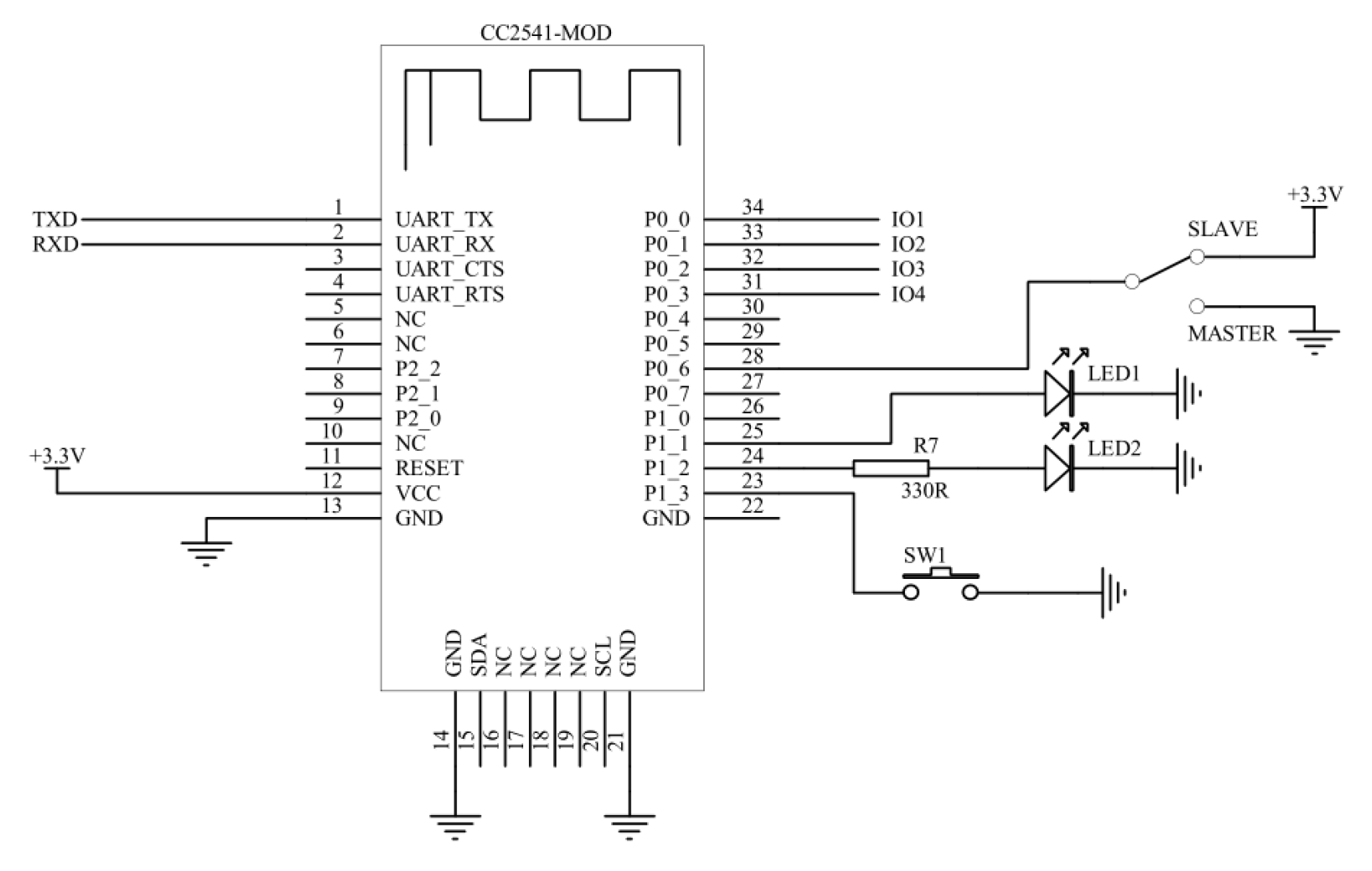
To support this theory further, the specification for the MLT-BT05 includes a schematic that describes pad 25 as a special pad whose signal behaves like a signal of the STATE pin.
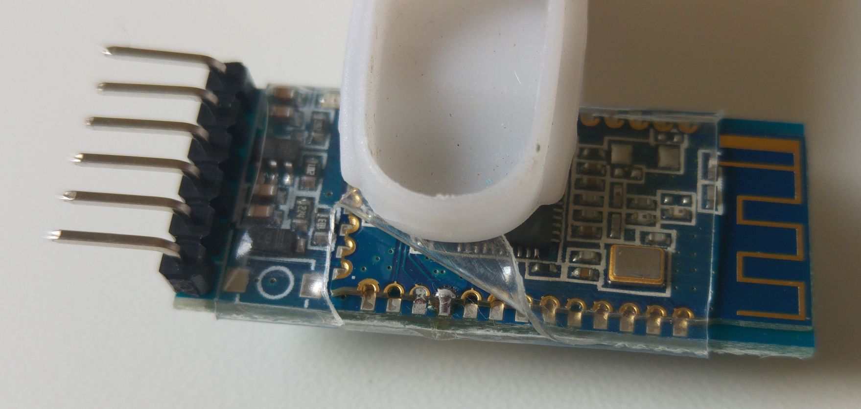
Unfortunately in order to verify this, one would need to remove or cut the shrink wrap. I couldn’t do it when I wrote the original article, but got an opportunity to do so later.
Cutting through
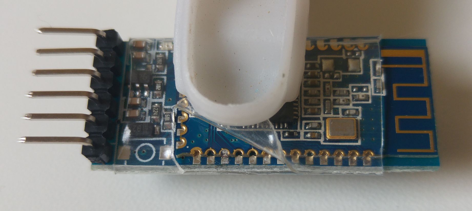
Once the pads were exposed it was easy to confirm with a DMM that:
- The STATE pin is routed to pad 25 on the breakout board
- The round pad 25 on the daughter board has the expected high/low signal depending on connection state
- The two are not connected 🙁
A quick solder job later

And some sticky tape to patch things back up
And we now have an MLT-BT05 module with a properly functioning STATE pin!
Why???
I couldn’t find any good explanation for making it this way. Either the manufacturer doesn’t know what he is doing or they are intentionally saving on the labor/solder by not adding another joint.
It could also be that I got 4 modules from a “bad” batch and that there are also properly soldered MLT-BT05 modules out there.
Neither of those possible explanations is any good. Let me know in the comments if you have any idea.
Still, for only 3$ per module it is up to you to decide if it is worth bothering with the fix or if it is better to pay a bit more and get some other option instead.
I own the MLT-BT05 clone (the one that reports AT+NAME=MLT-BT05-V4.0, recognizes only the command AT+PIN and does not recognize the command AT+PASS, and has only one oscillator on the daughterboard). I cut the plastic protection and used the multimeter continuity test to see on all three sides of the daughterboard if the contacts are soldered. I cannot be 100% sure but some of them seem that are not soldered. Moreover, on the two long sides of the daughterboard, the contacts seem to be somehow aligned with the corresponding solder contacts on the breakout board, but on the short side of the daughterboard (the one on the opposite side of the antenna side), the contacts are obviously out of alignment.
Do you think it would be a bad idea to desolder and resolder the entire daughterboard off/on the breakout board again ? I mean, ALL the contacts (2×13+8), just to be sure that nothing is left unsoldered.
Hi Mihai,
What you have to consider first, is whether your module is working correctly or not. If it is working ok I would suggest you don’t attempt to redo it. If it is not working ok, what is not working?
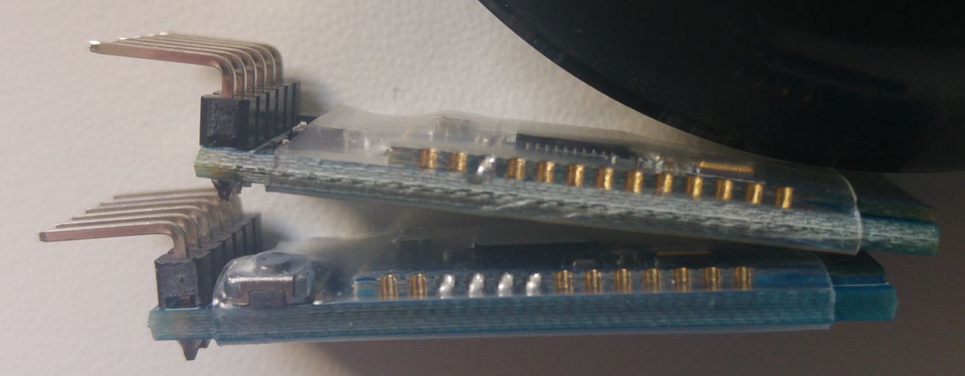
You should be able to identify which pads are soldered and which are not by a visual inspection. No need to test with a multi-meter. See example of soldered and not soldered pads here: http://blog.yavilevich.com/wp-content/uploads/2017/03/Solder-joints-MLT-vs-CC41-tn.jpg . Feel free to post a photo of your module so we can see its joints.
The pads on the short side of the daughter board are GND, SDA and some not-connected pads. None of these are usually used in a module like we are discussing here so it probably doesn’t matter whether they are aligned or not.
The small “open stamp”-like pads can be difficult to solder. If your soldering skills are good then you might improve the connections and the physical strength of the module by re-soldering the pads, but otherwise I wouldn’t risk it unless you need to fix the module.
I have question: a week ago I changed the BAUD rate, and forgot about it. And now
module does not respond to AT commands. How to hardware reset baud for clone hm-10?
Hi Zufar,
I am not familiar with an easy way to reset/change the baud without having AT command access.
There are only 5 baud options, so just try each and see if you get a response. Once you found the current value change to the default and keep it that way. No good reason to change the default value.
As I wrote:now
module does not respond any AT commands.
Ps I found on the official HM-10 (in datasheet) there is a System KEY function (PIO0)- it’s pin 23
Press if Low> 1000ms:
Module will reset to default configuration. Then restart
So I closed on the ground, but nothing happened
Hi.
I have a MLT-BT05 module and it doesn´t respond to all the AT commands. When I send it AT\R, it responds Ok, but if I send AT+HELP, the module responds “ERR”, also I cannot change the name or any of the settings. The module responds when I ask the name, the role o baud, but if I want to change any of these, for expample, AT+ROLE1\R, the module responds “ERR” or doesn’t do anything.
I don’t know why this is happnening, but I hope you can help me. Thanks.
Hi Armando,
What does https://github.com/ayavilevich/arduino-ble-ident-n-set say about this module? Can you take photos of the module and post some links here?
What was the initial name of the module?
salut , j’ai un probleme avc mlt b05 pendat l’apairage il me demande un cod et j’ai entre 1234 ne l’accepte pas puis j’ai essaye 0000 mm chose Svp aide moi
salut, try 123456 or 000000
Hello, i have a mlt-bt05 ble device that i am trying to send at commands to. the problem is that the ble device sends a “OK” response to “AT” command, but it doesn’t respond to any other AT command. For example: it doesn’t respond to “AT+HELP”, “AT+VERSION” or anything at all.
Hey Dovlet,
If it doesn’t respond to any AT commands (except for AT) how do you know it is an “mlt-bt05”?
Try ATI, ATH, AT?, etc. Maybe you can trigger it to make some kind of an response.
i downloaded an nrf ble scanner and got the name, i actually managed to get the responses from AT commands. Apparently i needed to send them in the “setup(){}” loop of the program, So i just reloaded again and again for every AT command i wanted to use, and got the response from the “Serial.write(ble_serial.read());” function. I don’t know if this behaviour is ok but it’s kind of strange. Other bluetooth devices used to give me responses just from manual typing in the Serial port during the “loop(){}” loop.
And I’ll definitely try those commands and tell you what i could find. Thank you!
In this case the issue is probably with your Arduino sketch.
Try to get another sketch where the Arduino device is acting as a proxy to the BLE.
Try: https://github.com/ayavilevich/arduino-ble-ident-n-set/
Mind different options for line termination CR, LF, etc.
I got the HC-10 BT module, when I load up the sketch.
I am seeing the following:-
Unexpected result of length=1
Arduino BLE module identification and setup sketch.
09:34:13.838 -> Interact with this interface using serial in CR&LF mode.
09:34:13.885 -> Enter the number of the RX pin on the Arduino, TX on the module [8] :
09:34:53.770 -> Enter the number of the TX pin on the Arduino, RX on the module [9] :
09:34:54.615 -> Enter the number of the State pin on the Arduino, State on the module (enter -1 if not present or not connected) [7] :
09:34:55.087 -> Opening serial connection to BLE module at pins: 8, 9, 7
09:34:55.087 -> Checking module state…
09:34:57.851 -> The signal on the state pin is LOW. This means the device is not connected and is in command mode.
09:34:57.851 -> Detecting module type
09:34:59.774 -> Arduino BLE module identification and setup sketch.
09:34:59.774 -> Interact with this interface using serial in CR&LF mode.
09:34:59.774 -> Enter the number of the RX pin on the Arduino, TX on the module [8] :
09:35:09.208 -> Enter the number of the TX pin on the Arduino, RX on the module [9] :
09:35:09.817 -> Enter the number of the State pin on the Arduino, State on the module (enter -1 if not present or not connected) [7] :
09:35:10.287 -> Opening serial connection to BLE module at pins: 8, 9, 7
09:35:10.287 -> Checking module state…
09:35:13.097 -> The signal on the state pin is LOW. This means the device is not connected and is in command mode.
09:35:13.097 -> Detecting module type
09:35:13.854 -> No response received from module.
09:35:13.854 -> Verify that the module is powered. Is the led blinking?
09:35:13.854 -> Check that pins are correctly connected and the right values were entered.
09:35:13.854 -> Are you using a logic voltage converter for a module that already has such logic on board?
09:35:13.854 -> Are you using a module that expects 3.3v logic? You might need to do logic convertion on Arduio’s TX pin (module’s RX pin).
09:35:13.854 -> Enter the number of the RX pin on the Arduino, TX on the module [8] :
09:35:33.593 -> Enter the number of the TX pin on the Arduino, RX on the module [9] :
09:35:34.625 -> Enter the number of the State pin on the Arduino, State on the module (enter -1 if not present or not connected) [7] :
09:35:35.703 -> Opening serial connection to BLE module at pins: 8, 9, 7
09:35:35.891 -> Checking module state…
09:35:38.662 -> The signal on the state pin is LOW. This means the device is not connected and is in command mode.
09:35:38.662 -> Detecting module type
09:35:38.894 -> Unexpected result of length=1
My guess is that the module is not connected correctly to the arduino.
Hi Arik. I have 3 of these modules with all pads soldered, so the STATE pin works OK. My issue is with the EN (enable) pin. It doesn’t work at all. The EN pin is connected through a 2.2K resistor to PO_0/PIO11 pin, and this pin is connected to a 10K pull down resistor to GND. Then VCC (3.3V from the output of its onboard regulator) is also connected to the onboard switch to this pin, i.e. the EN and PIO11 pins are pulled down until the switch is pressed, but nothing happens.
Any ideas about this issue? Thanks!
I am not surprised. Cost is number one factor in these modules. You can see in my photos they don’t even bother to have the button in most cases. Usually the EN logic is not implemented. I believe I have seen just one or two board types where it is present.
As a work around, you can always use a MOSFET to, externally, turn power on and off to the board.