Smoke detectors are simple and effective means for saving lives and reducing damage to property in case of a fire. You should use smoke detectors in your house even if your local regulations don’t require you to do so. All smoke detectors make a loud beeping alarm sound if smoke is detected, but some models will also emit a 433Mhz Radio Frequency (RF) signal.
Recently I have integrated several such detectors with Home Assistant (HA), a popular, open-source home automation software. This allows for various actions to be performed in case of an alarm, such as notifications, smart home actions and anything else HA integrations allow.
tl;dr, two Tasmota devices, one with an STX882 and one with SRX882 are installed and connected to HA using MQTT auto-discovery. A package of sensors, timers and automation flows is added to HA to handle alerts and perform actions in case of an alarm. An additional set of automation flows is added to perform hourly tests of the setup to make sure this works in case of a real emergency.
Introduction
This article will discuss HA, Tasmota, S[TR]X882 and the 433Mhz band specifically. If you want to follow the instructions here to the letter, you have to use these options. If you feel comfortable improvising, you can probably use different components and a different band, as long as you pick and choose correctly. The cost of the gateway components needed for the project can be as low as $6, not including smoke detectors, cables or enclosures (if that is your thing).
This project could be classified as a simple electronics DIY project. It needs some basic soldering and flashing. If you are not comfortable with this, you should look into more off-the-shelf solutions, such as a Sonoff RF Bridge. Take a look at this video tutorial to know more.
RF basics
The 433Mhz band is used here because it is a popular, unregulated RF frequency (see ISM band). Also, the lower frequency (i.e. compared to 2.4Ghz) allows for greater range, and easy coverage of a typical house, even with simple, low-cost and low-power receiver/transmitter devices.
The devices that we will support will be 433Mhz devices that use On-off keying (OOK), a simple method to send low bandwidth data over RF. Typically a device will send 24bits or something in that order. The data includes an id of the device and each device comes with a different, fixed id. Often few of those bits might represent state of buttons, such as when the device is a remote control. This method is popular with simple, non secure remotes. It is easy to duplicate the codes as you will see us doing.
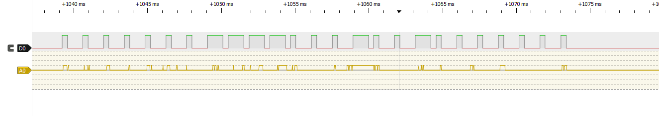
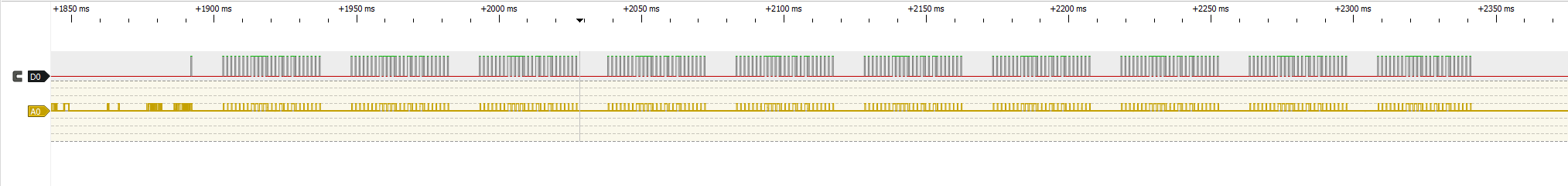
The bits are encoded in a set of pulses. Different protocols of 433Mhz on-off keying define different lengths of pulses for different binary digits. Typical length of such a pulse is about 500us. An RF code will be successfully received at the device when a sequence of pulses that matches a specific protocol’s pulse lengths is detected. The smoke sensors that I used transmit a code using the protocol of the EV1527 IC. But it doesn’t matter, we will implement an RF gateway that can decode a variety of on-off keying protocols.
What you will need
Home Assistant and an MQTT broker
This article assumes you have a working HA installation that you wish to integrate with. I will not cover general HA setup or installation. Please refer to HA setup if you need to.
You should also have an MQTT broker installed and configured. If you had used Tasmota in the past, then you must have already addressed this issue before, otherwise there are some instructions to follow.
Two Tasmota capable boards
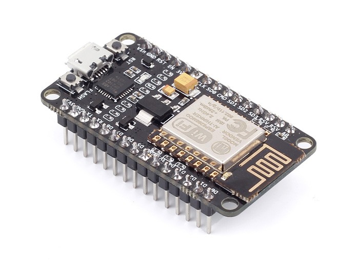
Tasmota is an open source firmware that runs on ESP8266 and now also on ESP32 micro-controllers. These are small, low-cost, Wi-Fi capable modules that integrate a processor, RAM, flash, IO and wireless functionality. The Tasmota firmware can be used to run a smart socket, sensors, relays and more. Whatever Tasmota operates is automatically integrated into HA using MQTT (a message transfer protocol).

This article assumes you are familiar with Tasmota’s basic flashing and configuration. If not, there are plenty of resources online. A good starter is Tasmota’s own page.
Tasmota implements RF functionality by using another library rc-switch. A fork of rc-switch with more options, by 1technophile, to be exact. One of the limitations of rc-switch is that it can’t send and receive at the same time. It is preferable to have the ability to send RF codes for testing and automated QA and this why I used two separate devices.
You can choose any compatible board as long as it has one pin available. Note that the SRX882 will most likely require 5V to operate properly, so make sure you can provide that. You can even add this to another existing Tasmota device or create a multi-sensor device. As a general rule, beginners should choose boards that include a USB connector, a 5V pin and a programming interface, such as NodeMCU, ESP32 DevKits or equivalent generic products. More advanced users can go for lower level devices such as an ESP-01S.
SRX882 433Mhz receiver and STX882 433Mhz transmitter
These are typically sold as a kit of a receiver, a transmitter and two antennas on ebay/aliexpress and similar sites. Note that antennas and pins might need to be soldered! It is an easy soldering task, but please take it into consideration.
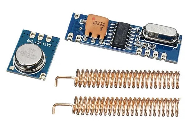
You can use something else, but this model is listed in Tasmota’s RF guide and works fine for me. What is important about this pair is that it doesn’t talk a specific OOK protocol, but rather just sends and receives the signal at a lower level. This allows us to capture any pulses and decode any valid protocols in software (using rc-switch).
A kit costs less than $2, so you might as well get two kits in case you need to troubleshoot.
One or more 433Mhz smoke detectors
Look for sensors that mention 433Mhz explicitly. I have seen listings that mention the code “EV1527”. This refers to a specific OOK protocol that was tested to work. Typically an RF enabled smoke detector will use a 9V battery. There are detectors with AA batteries, which operate at 3V but it seems that it is not enough for typical RF functionality.
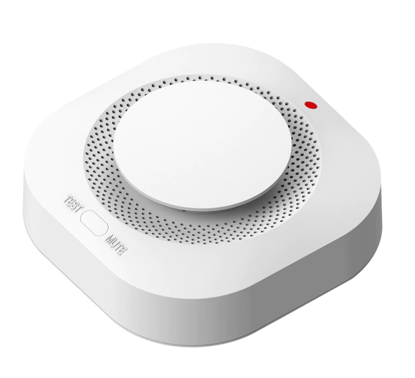
I tested two types of detectors that I purchased from China. Both seem to be white labels as there are different brands of what (at least externally) looks to be the same device.
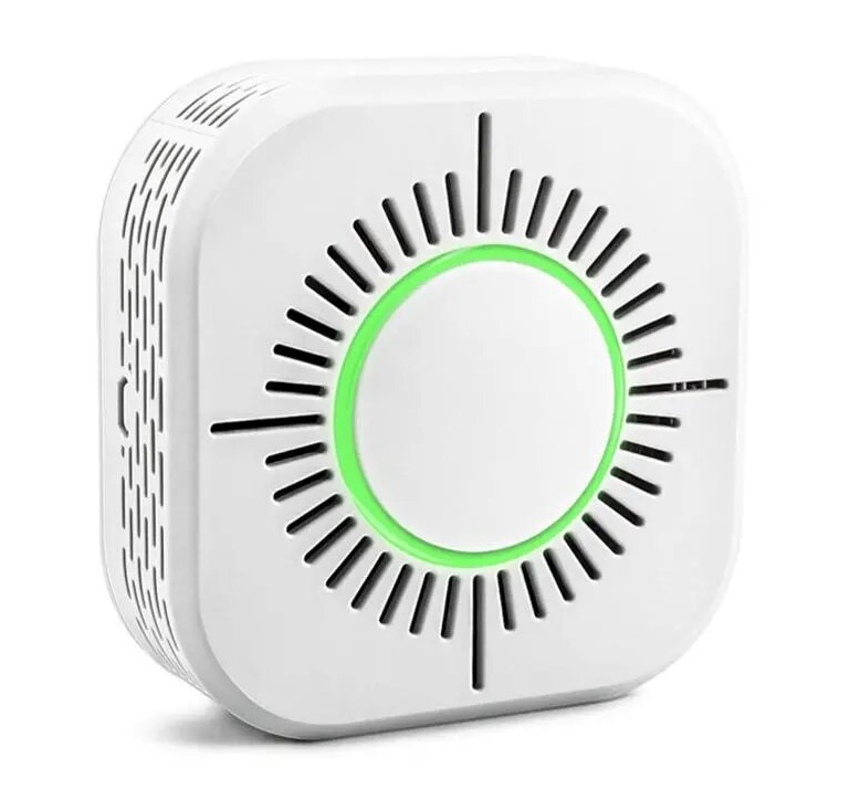
Both seem to work well. I conducted improvised smoke tests by burning a rubber band close to the detector. The detector on the right was MUCH easier to trigger with this kind of test so it seems to be more sensitive to smoke and is the that one I recommend. I couldn’t find differences with regards to RF, alarm, test function or other functionality. Both are also priced similarly. Note that you can often buy sets of several units with a discount.
Integrating the components
Tasmota and RF
First prepare two Tasmota devices. Flash tasmota-sensors or tasmota32-sensors to the boards depending on the type of micro controller. Configure name, hostname, wifi and MQTT parameters as you would normally do. I like to use Tasmotizer for this. I named mine “tasmota_rf” and tasmota_rf_test”. I will refer to them as RF device and RF test device below. Check that the devices register properly in HA.
Next, power off your Tasmotas and connect the RF modules. Perform the connection per the instructions from Tasmota’s documentation. You will need to select one data pin on each device. If you are not familiar with the pins, choose IO2 on the ESP8266 and either 13, 14, 25 or 26 on the ESP32. Other options should work, too, but be careful with pins that have special behavior, especially on the ESP32. Note, I connected STX882’s “+” pin to 3.3V and SRX882’s “CS” pin to 5V.
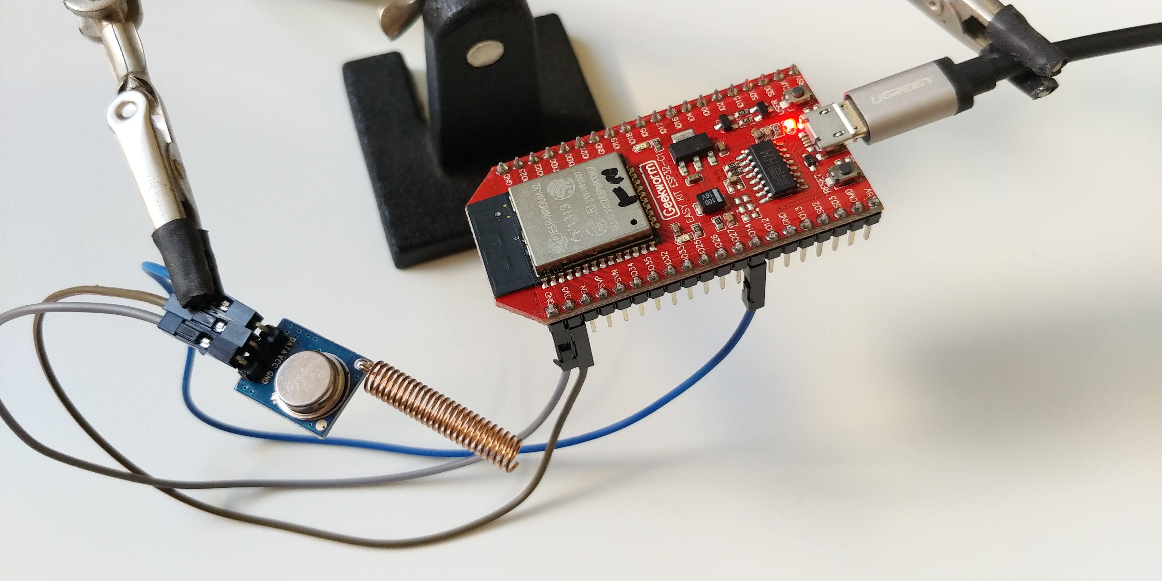
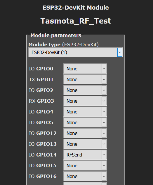
Power up the Tasmotas. Connect to the web interface, “Configuration”, “Configure Module” and define, for each device, the appropriate role to the data pin you used to connect the ESP to the RF module. For “RF device” assign a “RFSend” pin and for the “RF test device” assign a “RFrecv” pin.
Next, in the console of the “RF test device” issue command:
RfSend 1
it should respond with:
MQT: stat/tasmota_rf_test/RESULT = {"RFSend":"Done"}
and the console of the “RF device” should show:
MQT: tele/tasmota_rf/RESULT = {"Time":"2020-10-11T13:04:23","RfReceived":{"Data":"0x1","Bits":24,"Protocol":1,"Pulse":353}}
If this doesn’t work, check your wiring, and any error messages, if any. To further isolate the problem, try other remotes that you might have in your house. If you don’t mind the noise, try to run a test on the smoke detector. This should help you see if the problem is with your receiver or your transmitter.
Once you are able to send and receive signals using the Tasmota console, you are ready to configure the automation flows in HA.
Site survey
Simply run the test function on each of your smoke detectors until you see RfReceived messages in the console of the “RF device”.
Make a list of the data property in the message of each sensor. This is the unique code assigned to the detector.
Home assistant
Next, we need to configure HA. I used a package to encapsulate all our smoke detector logic in one file. HA configuration packages are a great way to separate functionality to individual files so that your configuration.yaml file is less of a mess.
If you don’t have a packages entry in your configuration.yaml add:
homeassistant:
  # packages folder
  packages: !include_dir_named packages
Then in your configuration folder (where configuration.yaml is), create a folder called packages. Inside of it create a file called smoke.yaml. Feel free to customize if you are an advanced user.
Add the following definitions in the smoke.yaml file (also in gist):
binary_sensor:
  - platform: mqtt
    name: "Room1 Smoke Detector"
    payload_on: "0x111111"
    payload_off: "0x111111off"
    device_class: smoke
    state_topic: "tele/tasmota_rf/RESULT"
    value_template: '{{ value_json.RfReceived.Data }}'
  - platform: mqtt
    name: "Room2 Smoke Detector"
    payload_on: "0x222222"
    payload_off: "0x222222off"
    device_class: smoke
    state_topic: "tele/tasmota_rf/RESULT"
    value_template: '{{ value_json.RfReceived.Data }}'
  - platform: mqtt
    name: "Test Smoke Detector"
    payload_on: "0x555555"
    payload_off: "0x555555off"
    device_class: smoke
    state_topic: "tele/tasmota_rf/RESULT"
    value_template: '{{ value_json.RfReceived.Data }}'

timer:
  room1_smoke_detector:
    duration: '00:00:05'
  room2_smoke_detector:
    duration: '00:00:05'
  test_smoke_detector:
    duration: '00:00:05'
  test_smoke_detector_check:
    duration: '00:00:04'

automation:
# room1
  - alias: Turn on room1 smoke sensor timer
    trigger:
      platform: mqtt
      topic: "tele/tasmota_rf/RESULT"
    condition:
      condition: template
      value_template: "{{ trigger.payload_json['RfReceived']['Data'] == '0x111111' }}"
    action:
      service: timer.start
      entity_id: timer.room1_smoke_detector
  - alias: Turn off room1 smoke sensor
    trigger:
      platform: event
      event_type: timer.finished
      event_data:
        entity_id: timer.room1_smoke_detector
    action:
      service: mqtt.publish
      data:
        topic: "tele/tasmota_rf/RESULT"
        payload: '{"RfReceived":{"Data":"0x111111off"}}'
        retain: "true"
  - alias: Notify about room1 smoke detector
    trigger:
    - entity_id: binary_sensor.room1_smoke_detector
      from: 'off'
      platform: state
      to: 'on'
    action:
    - service: persistent_notification.create
      data_template:
        title: Smoke detected
        message: "{{ trigger.entity_id }}"
#    - service: notify.mobile_app_PHONE
#      data_template:
#        title: Smoke detected
#        message: "{{ trigger.entity_id }}"
# room2 room
  - alias: Turn on room2 room smoke sensor timer
    trigger:
      platform: mqtt
      topic: "tele/tasmota_rf/RESULT"
    condition:
      condition: template
      value_template: "{{ trigger.payload_json['RfReceived']['Data'] == '0x222222' }}"
    action:
      service: timer.start
      entity_id: timer.room2_smoke_detector
  - alias: Turn off room2 room smoke sensor
    trigger:
      platform: event
      event_type: timer.finished
      event_data:
        entity_id: timer.room2_smoke_detector
    action:
      service: mqtt.publish
      data:
        topic: "tele/tasmota_rf/RESULT"
        payload: '{"RfReceived":{"Data":"0x222222off"}}'
        retain: "true"
  - alias: Notify about room2 room smoke detector
    trigger:
    - entity_id: binary_sensor.room2_room_smoke_detector
      from: 'off'
      platform: state
      to: 'on'
    action:
    - service: persistent_notification.create
      data_template:
        title: Smoke detected
        message: "{{ trigger.entity_id }}"
#    - service: notify.mobile_app_PHONE
#      data_template:
#        title: Smoke detected
#        message: "{{ trigger.entity_id }}"
# test sensor
  - alias: Turn on test smoke sensor timer
    trigger:
      platform: mqtt
      topic: "tele/tasmota_rf/RESULT"
    condition:
      condition: template
      value_template: "{{ trigger.payload_json['RfReceived']['Data'] == '0x555555' }}"
    action:
      service: timer.start
      entity_id: timer.test_smoke_detector
  - alias: Turn off test smoke sensor
    trigger:
      platform: event
      event_type: timer.finished
      event_data:
        entity_id: timer.test_smoke_detector
    action:
      service: mqtt.publish
      data:
        topic: "tele/tasmota_rf/RESULT"
        payload: '{"RfReceived":{"Data":"0x555555off"}}'
        retain: "true"
  - alias: Check if test smoke detector works
    trigger:
      platform: event
      event_type: timer.finished
      event_data:
        entity_id: timer.test_smoke_detector_check
    condition:
      - condition: state
        entity_id: binary_sensor.test_smoke_detector
        state: 'off'
    action:
    - service: persistent_notification.create
      data_template:
        title: RF Smoke detector check
        message: "FAILED"
#    - service: notify.mobile_app_PHONE
#      data_template:
#        title: RF Smoke detector check
#        message: "FAILED"
  - alias: Run RF test check
    trigger:
      platform: time_pattern
      minutes: 15
      seconds: 0
    action:
    - service: script.rf_test

script:
  rf_test:
    sequence:
    - service: timer.start
      entity_id: timer.test_smoke_detector_check
    - service: mqtt.publish
      data:
        topic: 'cmnd/tasmota_rf_test/RfSend'
        payload: '0x555555'
    - delay:
        seconds: 1 # wait a bit
    - service: mqtt.publish
      data:
        topic: 'cmnd/tasmota_rf_test/RfSend'
        payload: '0x555555'
    - delay:
        seconds: 1 # wait a bit
    - service: mqtt.publish
      data:
        topic: 'cmnd/tasmota_rf_test/RfSend'
        payload: '0x555555'
    - delay:
        seconds: 1 # wait a bit
    - service: mqtt.publish
      data:
        topic: 'cmnd/tasmota_rf_test/RfSend'
        payload: '0x555555'
This snippet defines logic for two smoke detectors (room1 and room2) and for a test detector with testing automation.
Change 0x111111 and 0x222222 to the codes of your actual smoke detectors. Duplicate room1 and room2 sections as many times as you need. The testing sensor and section can be used as-is as long as you don’t have a real device that uses the code 0x555555.
The code below defines a persistent_notification for each sensor, but you can add your own calls. I added a commented out section for sending a push notification to a mobile phone running the HA app. You can go crazy here, send SMS messages, make calls, send telegram messages, turn on lights, etc. You can also customize entity names and texts of messages if you want.
Troubleshooting
To have a good sense of what is going on, I suggest to add lovelace cards for this setup. I created a view for smoke/fire related sensors and added a card for each detector (including the test one).
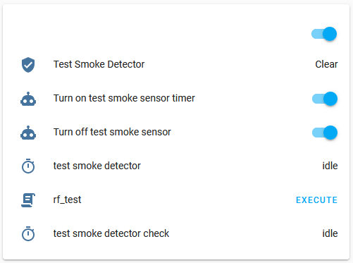
This way you can monitor what happens when a test runs or when an actual alarm sounds.
If a test suddenly fails I suggest the following checklist:
- Are devices powered and running?
- Are devices connected to Wi-Fi?
- Is the test device sending RF signals?
- Is the main device receiving RF signals?
- Does the timer of the relevant sensor start running?
Use the following tools:
- Tasmota Console
- MQTT client (such as MQTT Explorer MQTT.fx)
- HA logbook
Summary
Let me know if this works for you or if you have issues.
Latest version of the snippet will he updated above as well as in gist.
Stay safe.
Hi
Thank you for your very detailed procedure.
I did the same but using a Tasmotized Sonoff RF-Bridge.
Instead of using a “fake” payload_off: code I’ve used the off delay command, keeping the an alert active for 5 minutes.
“off_delay: 300”
I also bought the sensors you suggested, they work well and have a good build quality. Alerts always have the hex code 64 (xxxxx64) at the end.
According the Manual they also should sent a “Low Battery” alarm once a Day if the Battery is old. I wonder what the code is, so I could setup Low Battery alerts. I may have to test is If I find a old battery 🙂
I wonder what the code for these is
Hey Thomas,
For the record, my data doesn’t have hex code 64 at the end. Perhaps this is something that Sonoff RF adds.
Can you point me to the manual where it mentions the Low Battery signal? I wonder how it is done.
Hi Arik
I just ordered another 4 pieces…
Following is stated in the manual under “Technical Parameters”: (Chinese Manuals:-)
There is no specific model description, it just came in a Blue package named “Detector”
https://www.aliexpress.com/item/4001260167804.html?spm=a2g0s.9042311.0.0.27424c4dZewfqb
That’s the output from the Tasmota Console once I push the Test button (or used smoke):
MQT: tele/tasmota_AAAAAA/RESULT = {“Time”:”2021-02-24T16:13:04″,”RfReceived”:{“Sync”:12530,”Low”:420,”High”:1240,”Data”:”XXXX64″,”RfKey”:”None”}}
For the value “Data” the first 4 Bytes are a differed adresses of each detector, while the last two Bytes in my case is always 64 which seems to be the alert type.
My HA Integration (binary_sensor.yaml )
– platform: mqtt
name: “Smoke-Living”
state_topic: “tele/tasmota_AAAAAA/RESULT”
value_template: “{{value_json.RfReceived.Data}}”
payload_on: “XXXX64”
off_delay: 300
device_class: smoke
qos: 1
Sooner or later I will find out I expect to last 2 bytes to change in an event of low voltage.
Thanks Thomas
Hey Thomas,
Interesting info, thanks.
One of my detectors is like the one you linked to and indeed, its id ends with “64”. The other models don’t have the same format.
It is strange that the address is 16 bits and the 8 bits are fixed. Normally 1527 protocol has 20 bits for address and only 4 bits for “buttons” or data. Perhaps 6 can vary, for example if they allocate an auto-incrementing id to the the devices it might eventually change to 7.
I guess that “4” is the state to signal an alert. In this case other bits could signal battery low, i.e. “1”, “2” or “8”.
I will order few additional units of this kind and check them out. They are quite good.
I can suggest that you setup a notification on any code that starts with a known prefix regardless of the last byte. This way you will detect additional commands as they happen.
Hi Thomas,
You might be interested to know that I was able to capture a “low battery” code for the smoke detector.
When the detector is in a state of low battery it will emit a code ending in 62 (instead of 64) every 60K seconds (~16.5h).
Regards, Arik.
I’m using the first detector above with the green led. I have 10 of them.
The ON rf signal is a 24 bits always ending with a hex 6
And the OFF signal is a 23 bits always half of the ON signal.
So if ON is 0x666886. OFF is 0x333443.
Hi J-E,
I am not aware that a smoke detector has “on” and “off” signals.
I think that what you are seeing is just the code and its version shifted by one bit. Probably due to issues in sending and/or receiving the signal correctly.
Hi Arik
After you posted the information about the Battery low (62) I did an automation in HA. This morning (middle of the night ;-( ) The first alarm came.
So it works !
Regards Thomas
Hi , I have esp8266 and I have install tasmota sensor
http://ota.tasmota.com/tasmota/release/tasmota-sensors.bin
And I want to configure the recv module .
But when I enter to Configuration -> Configure Module there is no Module type ESP32-DevKit or ESP8266-DevKit , Does it matter what is the module type? Should I configure “Sonoff RF” ?
I have tried to Configure “Sonoff RF” and GPIO03 as RFrecv to I connect the RX module to RX pin in esp8266 , but when I was send to data with TX , I didn’t see any log into Console in receiver device
If you have a ESP8266 devkit then you should probably specify “generic” as the board type in Tasmota and then configure your pins manually. The configuration of the pins will depend on what modules you connect to your ESP and where.
HEllo Arik,
Thank you for your comprehensive documentations.
I have the smoke detectors with the green light in them. And connected them to my Home Assistant through a Tasmotized Sonoff RF-Bridge. All works find and the test signals come through correctly.
From your testing sequence I read that it isn’t possible to turn them on through HA. I would like this so if one is triggered by smoke all can be triggered by HA.
Hi Marc,
That is correct. You can’t turn the alarm on with an RF command. I believe these devices have no RF receiver. Just a transmitter.
Hi,
does anyone have experience with battery life time of model with green lights (EV1527)? My batteries did it for only one year. This is to expensive for 9V batteries IMHO.
Hi Horst, mine for less than 3 months (CW50 with green led)…I tried on 3 different models, same consumption…
Has someone the same trouble?