Previously I covered the HM-10 Bluetooth Low Energy (BLE) module and its clone, the CC41-A. Those are two popular modules that allow simple BLE communication through a serial interface and are handy with Arduinos and other hobby micro controllers. Make sure you read that article first as it provides important background for this curious update.
Recently I ordered a few BLE modules on ebay. The listing was using the name “HM-10” but the pictures where showing what is known as “CC41-A”. Though confusing, this happens with many items on ebay as it appears that “HM-10” lost its meaning as a specific model and is now more of a definition of a specific functionality. Having good experience with the CC41-A, I ordered a bunch.
CC41 Front
A few weeks later I get my package. Everything looks good at first and I try the modules. I quickly discover differences in behavior from what I have used in the past. Though very similar to the CC41-A, the modules I received seem to be a completely new model, “MLT-BT05”. The “MLT-BT05” looks a lot like a clone of the “CC41-A”, which amusingly is a clone of the “HM-10”. Unlike the “CC41-A”, the “MLT-BT05” is not a good clone and I will elaborate on this topic below.
Differences between “CC41-A” and “MLT-BT05”

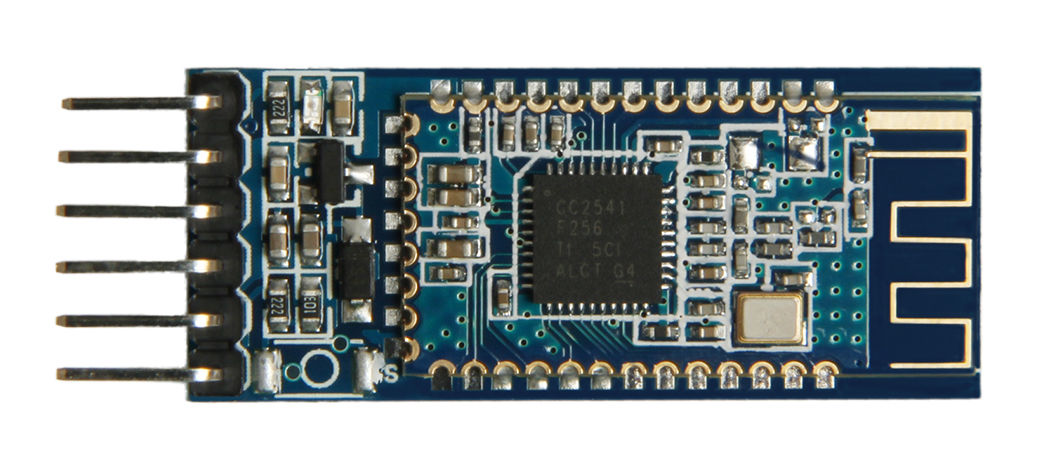
MLT-BT05 Front
The modules are different in hardware and in software (or rather firmware). Let’s discuss the differences and similarities one by one, starting with the physical differences.
The daughter board
This part looks identical. The similarity goes as far as having a place for a second oscillator but not having one soldered, which is a differentiator compared to the original “HM-10” (which has 2 oscillators). Same TI CC2541 chip, antenna, etc.
The breakout board
This part connects the daughter board to the pins. The PCB layout is different, with the main differentiator being a 5-pin voltage regulator compared to the 3-pin on in the “CC41-A”. Some other differences are in the passive components, mainly resistors.
Both modules have six 2.54mm pins for interfacing with the micro controller: STATE, RXD, TXD, GND, VCC, EN. However, the STATE pin of the “MLT-BT05” seems to be floating. This effectively means that there is no usable STATE pin. I haven’t tested the EN pin but power and UART pins seem to be working properly.
The lack of a working STATE pin in the “MLT-BT05” can be explained by fewer connections between the daughter board and the breakout board compared to the “CC41-A”. Specifically 1 vs 4 soldered pads on the bottom of the module.
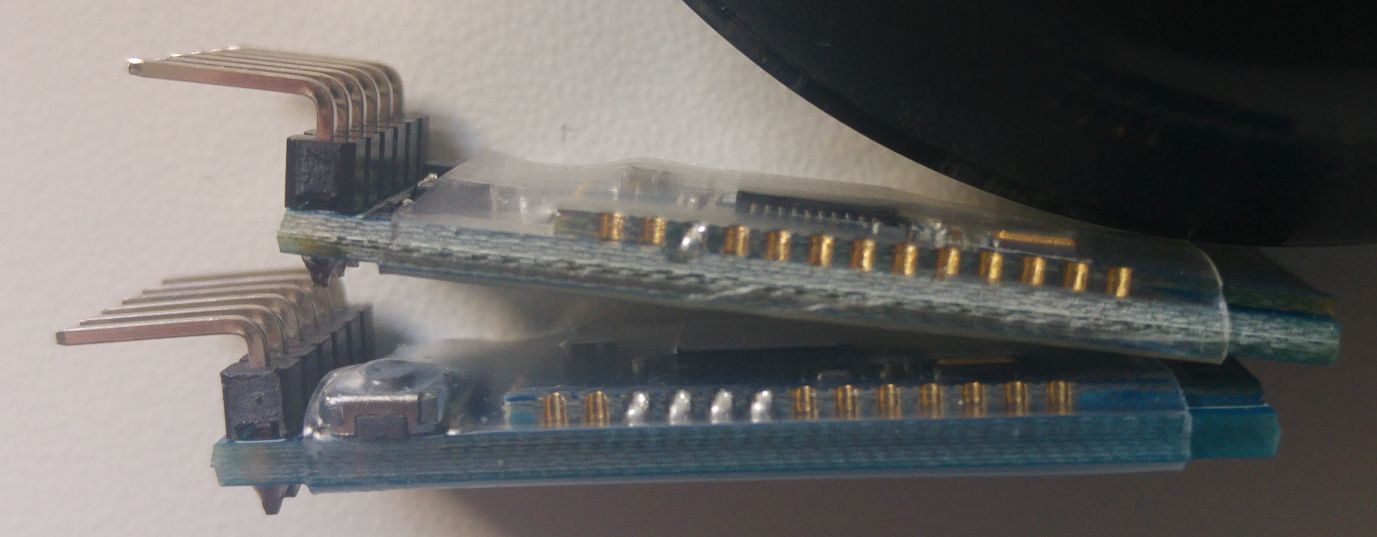
Solder joints MLT (top) vs CC41 (bottom)
Back side
The size is the same, but the PCB layout is completely different.
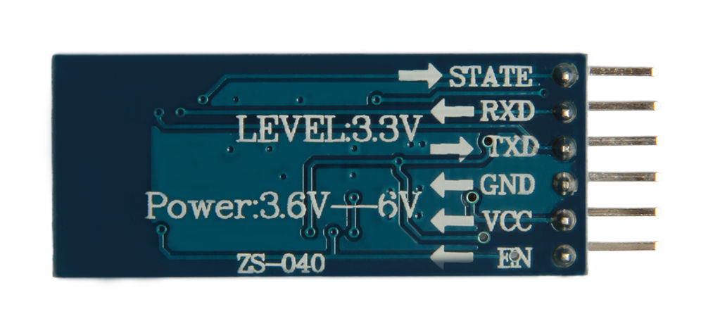
ZS-040, CC41 Back
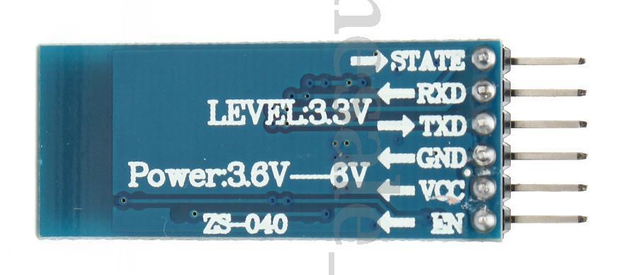
MLT-BT05 Back
The text is the same, but the “MLT-BT05” has a thicker silkscreen print than the “CC41-A”.
AT command syntax
Both modules expect a “carriage-return and new-line” at the end of commands. There is a subtle difference, though. The “MLT-BT05” expects its CR-NL to be sent immediately with the command, while the “CC41-A” will be happy even if there is a slight delay between the command and the CR-NL. That would indicate that the “CC41-A” is doing a better job buffering and that there are differences in the firmware of the modules.
Both modules also don’t need a ‘?’ at the end of the commands when querying for the current value. This essentially means that the two clones are closer to each other than to the original “HM-10”.
AT commands
AT+HELP of the “CC41-A”:
********************************************************************
* Command             Description
* ----------------------------------------------------------------
* AT                  Check if the command terminal work normally
* AT+RESET            Software reboot
* AT+VERSION          Get firmware, bluetooth, HCI and LMP version
* AT+HELP             List all the commands
* AT+NAME             Get/Set local device name
* AT+PIN              Get/Set pin code for pairing
* AT+PASS             Get/Set pin code for pairing
* AT+BAUD             Get/Set baud rate
* AT+LADDR            Get local bluetooth address
* AT+ADDR             Get local bluetooth address
* AT+DEFAULT          Restore factory default
* AT+RENEW            Restore factory default
* AT+STATE            Get current state
* AT+PWRM             Get/Set power on mode(low power)
* AT+POWE             Get/Set RF transmit power
* AT+SLEEP            Sleep mode
* AT+ROLE             Get/Set current role.
* AT+PARI             Get/Set UART parity bit.
* AT+STOP             Get/Set UART stop bit.
* AT+START            System start working.
* AT+IMME             System wait for command when power on.
* AT+IBEA             Switch iBeacon mode.
* AT+IBE0             Set iBeacon UUID 0.
* AT+IBE1             Set iBeacon UUID 1.
* AT+IBE2             Set iBeacon UUID 2.
* AT+IBE3             Set iBeacon UUID 3.
* AT+MARJ             Set iBeacon MARJ .
* AT+MINO             Set iBeacon MINO .
* AT+MEA              Set iBeacon MEA .
* AT+NOTI             Notify connection event .
* AT+UUID             Get/Set system SERVER_UUID .
* AT+CHAR             Get/Set system CHAR_UUID .
* -----------------------------------------------------------------*
* Note: (M) = The command support slave mode only.
* For more information, please visit http://www.bolutek.com
* Copyright@2013 www.bolutek.com. All rights reserved.
********************************************************************
AT+HELP of the “MLT-BT05”:
*******************************************************************
* Command             Description
*----------------------------------------------------------------
* AT                  Check if the command terminal work normally
* AT+DEFAULT          Restore factory default
* AT+BAUD             Get/Set baud rate
* AT+RESET            Software reboot
* AT+ROLE             Get/Set current role.
* AT+DISC             Disconnect connection
* AT+ADVEN            Broadcast switch
* AT+ADVI             Broadcast interval
* AT+NINTERVAL        Connection interval
* AT+POWE             Get/Set RF transmit power
* AT+NAME             Get/Set local device name
* AT+LADDR            Get local bluetooth address
* AT+VERSION          Get firmware, bluetooth, HCI and LMP version
* AT+TYPE             Binding and pairing settings
* AT+PIN              Get/Set pin code for pairing
* AT+UUID             Get/Set system SERVER_UUID .
* AT+CHAR             Get/Set system CHAR_UUID .
* AT+INQ              Search from device
* AT+RSLV             Read the scan list MAC address
* AT+CONN             Connected scan list device
* AT+CONA             Connection specified MAC
* AT+BAND             Binding from device
* AT+CLRBAND          Cancel binding
* AT+GETDCN           Number of scanned list devices
* AT+SLEEP            Sleep mode
* AT+HELP             List all the commands
* ---------------------------------------------------------------
******************************************************************
Some commands are the same and some are different. The “CC41-A” mentions its manufacturer, Bolutek, but the “MLT-BT05” mentions nothing about its origin.
Version and Name
Some commands offer us more information about the identity of the module. Here is a comparison of the responses to “AT+VERSION”:
“CC41-A”:
+VERSION=Firmware V3.0.6,Bluetooth V4.0 LE“MLT-BT05”:
MLT-BT05-V4.0Here is a comparison of the responses to “AT+NAME” with the default name set in the module:
“CC41-A”:
+NAME=BT05“MLT-BT05”:
+NAME=MLT-BT05Documentation about the “MLT-BT05”
I wasn’t able to find a lot of data about this module online. I found a zip file with stuff for the “MLT-BT04 V4” at what seems to be Baidu cloud file hosting. It included some BLE software and two PDFs in Chinese. An “MLT-BT05 4.0 AT-commands” document and an “MLT-BT05 4.0 datasheet”. Both useful to get some additional information and readable with Google Translate. It comes as no surprise that, once again, the files are lacking any information on the manufacturer. If you aware of any additional documentation, please mention it in the comments.
I have added the “MLT-BT05” to the arduino-ble-ident-n-set project, which should allow you to identify and configure your different BLE modules easily.
Is this a good clone of clone?
Assuming the practice of having and using clones doesn’t bother us, what will be important is whether the clone has the functionality that we expect. In this case, the “MLT-BT05” failed me big time. A module that looks like a module with a STATE pin but having a floating pin instead is not a proper clone and in my opinion is not truthful.
Update: The failure is due to a bad job of assembling the module. Can be fixed by a solder connection between the daughter board and the breakout board. Not a direct defect of the “MLT-BT05” and in fact, lately I am getting “CC41” modules with the same breakout and defect suggesting the same low-quality assembly facility that uses whatever boards it can get. Keep reading for the details and the fix.
Surely, if you are using the module in a way such that you are not using the STATE pin, then this might be an option for you. How you would be doing that without any ill effects is an interesting question.
Doing safe communications with a module like this, without knowing your connection state, is bad practice. The reason for that is that the serial communication line between the module and the micro controller is used both for commands and for data. The connection state determines whether we are in command mode or data mode. Not knowing the current state/mode could result in sending data that will be interpreted as commands and vice versa.
There are communication modules without a STATE pin, but those have a way to switch modes and query for current connection state with AT commands. For example Adafruit Flora Bluefruit LE. Perhaps the “MLT-BL05” can get such functionality in a firmware update one day.
Amusingly, the AT commands document mentions a command that is absent from AT+HELP listing. The AT+GETSTAT which should return 0 for “disconnected” and 1 for “connected”. What is amusing is that commands can only be sent while in disconnected state, so I am not sure if there is a “non-silly” way of using this command and getting something other than “0”.
Fixing the STATE pin in MLT-BL05 in hardware
Reading the datasheet of the module we find the following diagram:
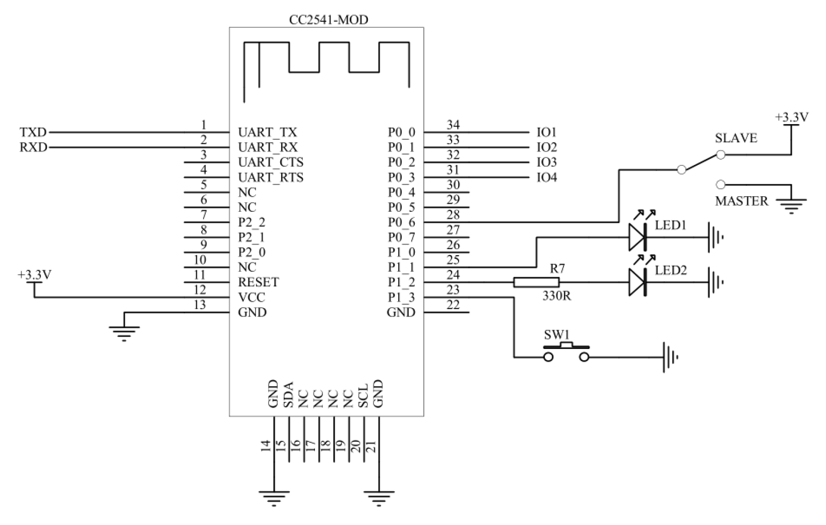
MLT-BL05 diagram
Out of all the pads on the right side of the board, the module comes with only pad 24 (P1_2) soldered. This pad is powering a led that is blinking in different ways depending on mode and role.
The documentation discusses pad 25 (P1_1) and describes it as HIGH on “connected” and LOW on “disconnected”. Exactly how STATE pin should perform. So is this a case of “doing one solder joint less”? Or is there some deeper reasoning behind that due to firmware issues or PCB layout? The module is in shrink-wrap, so no knowing without opening it up. Sounds like an interesting thing to investigate and write about in another blog post.
Will keep you updated. If you find out any interesting information about this module, please share in the comments below.
Update: Fixing the STATE pin of the MLT-BT05 is possible.
Thanks for the info, I got one of these off eBay expecting a CC41-A.
I can live without the STATE pin but I needed more firmware functionality for iBeacon support, so I just wanted to point out that its easy to flash the official HM-10 firmware on these boards as per https://forum.arduino.cc/index.php?topic=393655
Hi Joe, thanks for the info.
A quick spoiler, in case you want the STATE pin functionality. I was able to make it work by soldering the missing solder joint between the module board and the breakout board. I will post a detailed article with pics at a later time.
Pingback: Fixing a bad STATE pin on an MLT-BT05 BLE module | Arik Yavilevich's blog
Hello, I have a question. How do I have to configure MLTBT05 to connect it to android BT terminal? A have a arduino Uno and although the phone it self sees the shield, the app wont connect to it/
Thanks in advance.
Hi Stefan, what kind of “android BT terminal” are you using? If this a kind of Bluetooth Low Energy (BLE) terminal or a regular Bluetooth serial terminal? Try “nRF connect” app by Nordic for BLE modules such as the MLT-BT05.
Hi Arik, thank you for doing an amazing job! Its now clear that Technion wasn’t in vain :+>. I am trying to use your “arduino-ble-ident-n-set” project to talk to my MLT-BL05 clone. Unfortunately I can’t load the project to my Arduino Nano board via Arduino IDE. Do you have an idea of what might be the problem ?
Regards,
Albert
Hi Abert, greetings to the EE department. 😉
Can you load other projects to your Nano, such as the “blink” sketch?
What happens when you try to upload “arduino-ble-ident-n-set”? Do you get some error?
Hi Arik,
I have successfully uploaded the your sketch. There is a different issue though. When the Arduino Nano TX and RX are connected to the ZS-040 RX & TX I can ‘t upload the sketch. That was initially the problem. When I disconnect I am able to see the set up of your program prompting me with Qs. But as I connect the RX & TX of Nano board and ZS-040 the TX led on the Nano board goes red and your program hangs. Thus the interaction via Arduino serial monitor is frozen.
Any ideas ?
Sure, by Nano TX and RX pins you refer to D0 and D1 pins. Those are special. If you look in the sketch you can see that it is written to work with the BLE serial through ports 8 and 9 (by default). It does that with a technique called SoftwareSerial. You can’t use your D0 and D1 pins both for serial to the module and serial to the PC/USB. Choose different pair of pins for the module. Review information about software serial and hardware serial capabilities of the Arduino. Don’t forget to convert the logic signal to 3.3V if your module requires so. Good luck.
Thank Arik,
It was very helpful, but a bit too late. Before I got your response I came across the following tutorial from Hexor and YouTube video who basically explains how to turn your ZS-040 into HM-10 by bootloading an appropriate firmware. It worked OK for all the guys in the forum except me and a few others. Now I am looking for a way to boot with factory definitions, are you familiar with a way doing so ?
Regards
Hey Albert, I don’t know a way to boot to factory definitions. You might try to flash the original firmware if you can find a download of it.
Your description is very low on details. What happened during the flashing process? Why did you try to flash another firmware? Were you able to communicate with the board before the flashing? Are you able to communicate with the board after flashing? What Arduino are you using? How are the Arduino and module connected? How do you convert logic levels? And more…
Arik,
I will answer your questions one by one:
Q:What happened during the flashing process?
A:This link describes the flashing from A-Z. The flashing went appearntly smooth but the at end of the process the led on the ZS-040 should blink. It doesn’t blink on my board any more. It’s simply off and the board doesn’t pear.
Q: Why did you try to flash another firmware?
A: You said State pin is essential and could be revived via Firmware update.
Q:Were you able to communicate with the board before the flashing?
A: I don’t know because I used the TX-0 & RX-1 pins which are used to communicate with the PC via USB (as you said).
Q:Are you able to communicate with the board after flashing?
A:When I run your sketch I get the following answer: “No response received from module.”
Q:What Arduino are you using?
A:I am using Arduino Nano.
Q:How are the Arduino and module connected?
A:Its connected via wires on a breadboard.
Q:How do you convert logic levels?
A:I used voltage divider on the TX of the Arduino (2.2ohm vs 1 ohm)
I hope its more detailed now,
Albert
Hey Albert, much more clear now, thanks. I assume that before flashing the led was flashing and the module was pairing, correct?
When doing the flashing, did you perform logic level conversion as well? Can you post a schematic of the flashing process? You might have flashed all zeros or all ones if there was no conversion.
No other ideas for now but intrigued as to what happened. Good that these are just $3 ;).
Hi, I have a query. I was able to connect to my MLT-BT05 module by nRF connect app. But, I couldn’t send or receive data. I used UART function of nRF toolbox, but it replied, “the device doesn’t have required services”. What should I do next? Please, guide me further. Thanks in advance.
Hi Ashish,
When the module has no BLE master connected to it (nRF disconnected), are you able to send AT commands to the module through the serial connection? If not, figure out that first.
If you have commands working, try to enter into data mode and send packets of data from your phone to the serial end using BLE service “0000ffe0-0000-1000-8000-00805f9b34fb” and characteristic “0000ffe1-0000-1000-8000-00805f9b34fb”.
Yes, I can send the AT commands through Arduino IDE.
Which AT command is used for data mode?
Hi,
When the module is connected you automatically switch to data mode. You can try issuing AT commands once connected and see the behavior. During data mode, any data you send through the serial connection (“Arduino IDE”) is sent to the BLE master that is connected. You need to subscribe to notifications on the characteristic I mentioned above. Similarly, any values you write to the characteristic on the master will be received on the serial connection.
Thanks for the help. Can send data now.
However, can you please suggest me a way to transmit some analog value from arduino via bluetooth to the phone.
Thanks again.
Hi, if you can send data over BLE then you are already able to transmit analog values or any other strings or bytes. Are you asking about an alternative to nRF that would be a more convenient UI for looking at a stream of values? I can’t recommend one, but search for “BLE terminal” on the app store and you will some options. “BleTerm” looks promising, though I didn’t try it.
I mean, how to store the continuous values on the phone?
Anyway, thanks man.
I bugged you a lot.
Ohh, I see. Well, I don’t think there is any built-in support for storing the data over BLE. If there is no app for that already then you might need to make one. 😉
Did you find out the default pin for the bluetooth connection?
Hi Peter, I am not sure I understand what you refer to as “the default pin”. I did find out that you can fix the STATE pin with some soldering. See http://blog.yavilevich.com/2017/04/fixing-a-bad-state-pin-on-an-mlt-bt05-ble-module/
Arik, I ran one of the Chinese pdfs you found through google translate and the translation gave slightly more information in which you might be interested. You should try it with others.
https://translate.google.com/translate?sl=zh-CN&tl=en&js=y&prev=_t&hl=en&ie=UTF-8&u=http%3A%2F%2Fblog.yavilevich.com%2Fwp-content%2Fuploads%2F2017%2F03%2FMLT-BT05-Datasheet-Chinese.pdf&edit-text=
Hi Cam, you are absolutely right. I have done that originally to learn about the different pins. If you find out any additional information that you think is important or interesting please post it in the comments.
It’s interesting, i just got my clone of a clone, and indeed it had a solder joint missing. I soldered it as shown below, continuity tests showed you were indeed right as it’s pulled out to the state pin. I could use your software to change the name and passcode, but when i paired to my computer it never asked for a passcode, and regardless of what i do, my phone keeps instantly saying ‘connection rejected/terminated’ as soon as i click on the object to pair. Weird, i’m certain it has nothing to do with your code, must be a faulty unit.
https://drive.google.com/file/d/1NaCd54A8Q-Z8C-RTwy6wwjKvSRseEWI8Zg/view?usp=sharing
I used AT+RENEW DEFAULT and now your code shows this, which i found a bit odd:
https://www.dropbox.com/s/2mir82rjqk3nn0a/Screenshot%202017-06-23%2014.55.20.png?dl=0
I guess it’s money back time.
(I discussed this issue with Ben offline, including a summary for the readers)
Based on the firmware, this is the CC41 clone of the HM-10 (the one made by Bolutek). The breakout board is new and was not featured on this site previously. Unfortunately it seems that the entity assembling these modules didn’t solder the STATE connection (same entity that makes the MLT clones?).
Passcode/Pin is not relevant and not implemented on the clones, as far as I have seen. Only the original has some sort of authentication.
Pairing with the phone is not needed, as these are BLE modules. Need to use the right BLE app on the phone. For example ‘nRF connect’ on Android.
Bad AT mode communication is probably due to power or wiring issues. Worked ok later.
Ben, please update if there are updates.
Hello, All,
I’m trying to access MLT-BT05-V4.0 in Master mode to HEXIWEAR (wearable watch supporting Bluetooth v4.1). Scanning for the watch, I can’t see it at all, tried many settings, but probbaly I don’t understand the operation enough. Do you have any idea what could be the reason that I can’t find it? Is there something with the UUID/Characteristic sizes, because I see ot the MLT-BT05 that these are 16 bits wide. I will be very thankful for any help..
Hi NYanakiev,
How are you scanning for it? Have you tried giving it a command to connect to the watch based on MAC without scanning?
Here are some points:
1) Try “nRF Connect for Mobile” or similar app on an Android smartphone to see if you can find the watch through other methods. Also check that you can connect to the watch and see the services.
2) It might be possible that the watch advertising interval is too infrequent for the MLT to find it.
3) I have not tried to use an MLT in master mode, but generally, service discovery happens after connection is successful, so differences in service UUID should not be a factor in connecting.
4) 16bit IDs are ok in the standard. There are default values for the other bits. Effectively you are only specifying part of the UUID.
5) The MLT has firmware that only lets it read and write one characteristic in a “serial-like” way. It might not be compatible with just any other BLE device. Try to connect to another MLT in peripheral mode.
Hi, Arik Yavilevich,
Thank you for the suggestion to connect directly with passing the MAC address!
That succeeded from 1st time! Obviously the searching mechanism (AT+INQ) doesn’t compy between the MLT-BT05 and the HEXIWEAR clock. I am surprised that worked, the next step is to transfer meaningful data! 🙂 Thanks again !
ps. check my blog, I will describe how to pair this device with Arduino, since I can’t find such project in the web.
http://nikosarea.blogspot.bg/2017/07/hexiwear-and-mlt-bt05-bluetooth-ble.html
Hi Niko,
Cool wearable device.
Looking forward to see your experiments with connecting the watch to Arduino. I have a feeling it won’t be easy with an MLT or any HM-10 clone because of the way they are implemented in a limited way with regards to BLE GATT services and categories. Those modules also not very good with authentication.
In case you haven’t seen this already, take a look at this post dealing with connecting a RasPi to Hexiwear: https://mcuoneclipse.com/2016/12/19/tutorial-ble-pairing-the-raspberry-pi-3-model-b-with-hexiwear/
Good luck!
For what’s it’s worth I just got a MLT-BT05 from Yourduino.com and the STATUS pin is working fine.
Hi Noah,
Thanks for your note. The difficulty is that it may be a working version one time and a “limited” version the other time. Could you post a photo of the module and a link to the product page?
Of course, product site is http://www.yourduino.com/sunshop/index.php?l=product_detail&p=529. Images are at https://drive.google.com/open?id=0B2019MF9pwzQZUJ5cTYxdlhZb2M.
Hey there. I’m using the MLT-bt05’s on Arduino Unos. I’m habing connection issues where they appear to pair with each for a few seconds then unpair (assuming the indicator light on these behave the same as a HM10). Is this a defect with these units?
Hi Phil,
For the HM10 clones, the light blinks when the device is not connected and the light is on when the device is connected.
You can also check the STATE pin to see if you have a connection or not. The pin is HIGH when the device is connected. You need to have a working STATE pin to try that. Some devices come with the STATE pin disconnected.
This sure as fck helped me a lot.
Thanx Arik!!
Hi Timo, glad to hear. 🙂
Great Article !
I have a MLT-BT05-V4.1 Board here but it’s not working at all. Well, AT-Commands are working but neither my MacBook nor my iPhone is able to “see” the device.
Also tried AT+ROLE1 and AT+INQ but no results.
Have you got any information about the V4.1 (NOT 4.0)? Google only returns about 4 resources in Russian and far-eastern language …
I’m thinking about flashing the genuine firmware – but would welcome using the module “as-it-is” if possible.
Additional information: On the backside there is a printing “JDY-09” and some Chinese characters
Hi Phil,
How are you trying to see the device on your iPhone? You should try to use a BLE scanner app for that. Is there a led on the board? What is its status?
With regards to V4.1 or JDY-09, I have not encountered such boards. Can you upload photos from both sides and a link to the source of the board? Thanks.
Hi Arik,
first of all, thanks for all the information and research, such a great job.
I recently purchased an MLT-BT05 on ebay, it was advertised as:”AT-09 Bluetooth 4.0 UART Modulo Transceptor BLE CC2540 CC2541 HM-10 MLT-BT05″
I didn’t research a lot before buying so I got it, as a start board for my final project.
I have been able to communicate through at commands with the serial monitor in arduino ide. But it only replies when I append \r at the end to the at command . I have marked both NL&CR on the ide, but I need to add “\r” in order to make it understand the command.
I show you somer examples.
BTserial started at 9600
>AT+NAME\r
+NAME=MLT-BT05
>AT\r
OK
>AT+VERSION
>AT+VERSION\r
MLT-BT05-V4.1
>AT+LADDR\r
ERR
As you see it returns an “ERR” when I ask for the address.
By the way, I have a led connected at the state pin and it is on when connected through apps, I have tested BLEScanner,Serial Bluetooth, nrf connect, and all of them turn the led on when connected. They also find the MLT-BT05 default profile and the services .
Now some questions, I hope that you can answer.
Is it worth to try to flash some HM-10 firmware to get better response of the at commands and the tools provided?
What tool may I use in order to create or modify Gatt profiles?
Thanks again for sharing your work and time.
Hi Gonzalo,
Interesting update. You seem to have one of the newer V4.1 MLT-BT05, as opposed to the V4.0 ones I have and covered before.
Perhaps they made changes to the firmware and changed the terminating character. Unfortunately I have no such module to test. Try different terminators to see what works.
Can you provide a link where you got this from and photos of the module? I would like to compare to the ones I have.
Hi Gonzalo,
Recently i have purchased 2nos Bluetooth module. it was advertised as: AT-09 Bluetooth 4.0 UART Transceiver Module CC2541 Compatible with HM-10. Module is not as actual i was thought. You post is helpful to me. Thank you for your post.
Actually my application is 1 module is host and other module is slave, connect to each other and data transmit to each other.
My module name is : +NAME=MLT-BT05
firmware Ver : MLT-BT05-V4.4.
Enquiry AT command is working but Set AT command is giving : ERR.
I am sending command “AT+ROLE1\r” for making module in master mode.
But reply with ERR.
Same problem with Baud rate change command.
What is the problem??
Any body have worked on this module. Please help to me.
Hi Kameshwar,
Did you try https://github.com/ayavilevich/arduino-ble-ident-n-set
Also, not sure why inquiry commands are working with just \r but you probably need to send \r\n as EOL after the command.
Hi Arik,
Thanks for the reply. Surprisingly it is working for inquiry with only \r. Also i am using STM micro controller uart to interface bluetooth module.But i am not able to set module in Master mode.
Bluetooth module will work after increase its firmware version with the help of HMSoft exe??
Then my module will be compatible with HM10??
I don’t think HMSoft.exe will work for a non HM module. You might be able to flash HM firmware with a programmer, but it is quite a lot of work. Probably easier to get a different module.
Dear Arik,
Thanks for the sending link https://github.com/ayavilevich/arduino-ble-ident-n-set
arduino-ble-ident-n-set is working and i am able to change its role.
In my module default baud rate is 4 mean 9600. And i have change to 0 and module reply with +Baud0. But baud rate of the module has not changes still 9600. It is module limitation?? In datasheet showing module support also 115200. Have you checked module MLT-BT05-V4.4 supports Baud rate 115200??
Hey, sorry, I don’t know. I haven’t checked this one yet.
Hi Arik,
thanks for replying.
The link where I got the module is the following:
https://www.ebay.es/itm/AT-09-Bluetooth-4-0-UART-Modulo-Transceptor-BLE-CC2540-CC2541-HM-10-MLT-BT05/222141455325?ssPageName=STRK%3AMEBIDX%3AIT&_trksid=p2057872.m2749.l2649
I tried to send to you some pictures through wetransfer.
Do you tyhink I could use bluetooth developer studio to work on the custom profiles with this module??
Thanks again for your help
Gonzalo
Hi Arik,
here´s th elink to the pictures, the email I sent to, was rejected.
They stay thers for 7 days.
https://we.tl/sed0SXi5vk
Hi Gonzalo,
Thanks for the details. I see this is something sold by a Spanish seller. That could explain why I have not seen these before.
The breakout board is like one I have but purchased some time ago. Seems like it is soldered well. The daughter board is a HM-10 clone. Based on what you mentioned, the firmware is MLT_BT05 V4.1 .
We see more and more different breakout/daughter/firmware combinations coming up.
With regards to modifying gatt profiles, that depends on what you want to modify. These modules are designed as serial-port-protocol modules and all the known HM-10 firmwares are doing just that. Some will allow you to change the UUID of the service or characteristic, but there are no commands for adding characteristics, etc. I recall a specific firmware (perhaps original HM-10) that allows to control GPIO via textual commands over the serial connection without gatt changes.
If you want custom gatt profiles you will need to write and compile your own firmware that will do what you need. Normally you would use TI’s development toolkit. Perhaps “bluetooth developer studio” can help you do that easily, I don’t know.
To flash a new firmware on the chip you would need a programmer for TI chips (CC Debugger) or to flash an Arduino with CC Debugger code. Then you need to identify the Debug data, Debug clock, Reset, Vcc and Gnd pins on your board and connect those to the programmer.
Ok, Arik thanks for your reply.
Thanks for letting me clear that I would have to compile a new firmware. That´s what I thought. No chance with the Bluetooth Developer Studio, TI don´t have the plugin for the CC2451 as I read in a post the following :
“The TI plugin is for SDKv2.1. I will see if this can be updated to make it more clear that it’s for CC2640 only. There is no option to generate code that is 100% compatible with CC2541 / BLE SDK v1.4.x.”
Here is the link:
https://e2e.ti.com/support/wireless_connectivity/bluetooth_low_energy/f/538/p/513091/1865348
I already read about cc-debugger, but I didn´t know I had the chance to use the arduino to flash it with cc debugger code.
Anyway, I guess that if I finally need to write those new profiles, it will be less cost effective to get a module compatible with BDS and easily updatable. Perhaps in the future with no endlines it would be great to give a try to compile my own firmware.
Thanks for all the information, thanks for answering so fast and thanks for your help.
Great job please keep up this incredible effort .
Cheers
Gonzalo
Hi Ari,
I have finally managed to get the module working. I don´t know why , but now I have uploaded a simple sketch to comunicate with the module, and it works perfect. No need to append the “\n” to launch the AT commands , and all the AT commands get successfull when sent. So I guess my code was wrong, because the hardware connections are the same. So I thougt to post this comment, just in case someone was thinking about getting the module. It works as it should.
Hi Gonzalo, thanks for the update and the clarification. LMK if you find new types of clone modules.
Hi Arik
thank you for your comments about MLT-BT05.
I am just beginner about arduino.
so I want to find many information on website.
and this blog is very good for me.
and… I have a question.
now I bought BLE module
that time I think it’s HM-10.
but after test it with PC, it’s “MLT-BT05 V4.1”
thanks to this site, many questions is solved.
I want to find around devices.
of course, android phone app “BLE scanner” can find few devices.
but this MLT-BT05 V4.1 can’t find this devices.
I wrote at command as “AT+INQ” but reply is “OK” and then after 10seconds “+INQE”.
I read your some reply “use direct MAC address”
but I don’t know how can I send command “direct MAC address”
could you help us about this?
I found AT command “AT+CONA123456789012” for direct mac address connection.
this device is “SENSOR”.
so I want to received data from this device.
could you help me how can I received this sensor data on BLE module?
Hi Mr.Kang,
Happy you found the info useful. Can you tell me where you purchased the V4.1 module? I am trying to get my hand on these.
Please see this translated MLT-BT05 AT commands document http://denethor.wlu.ca/arduino/MLT-BT05-AT-commands-TRANSLATED.pdf
It should be applicable for your module.
You can see that commands have parameters, specifically AT+INQ needs to be passed 1 or 0. It will then show a numbered result list. You can use the numbers in the list to connect by using AT+CONN[id]. It doesn’t seem like you can just connect to another device by providing a MAC address directly. Also, you would need to be in “Master mode” first using AT+ROLE1.
It is important to mention that the HM-10 family of modules are not generic BLE modules. They are serial line replacement and so are limited and probably can’t interface with most other BLE devices that expose different services/characteristics. I have not tested this, but they are most likely able to connect only to other HM-10 modules (or compatibles). Please check it out and let us know in the comments what you find out.
thank you comments.
http://www.sunhokey.com/product/60351807361-802675176/HM_10_module.html?spm=a2700.8304367.prewdfa4cf.4.4ee1ff06JFyglD
this site is my bought site about MLT-BT05-V4.1.
if send command “AT+INQ1” or “AT+INQ0”, return is “ERR” only even though “AT+ROLE1” as master mode.
so can’t connect AT+CONN[id]..
So I used “AT+CONA0050c26c9607” command direct connection.
return is “OK”
and “AT+BAND0050c26c9607” command returned “OK”
but “AT+RSLV” is ERR.
and “AT+GETDCN” command is returned “+GETDCN:0”
I don’t know .. how can I progressed next step for communication this device.
this device is “DOOR OPEN SENSOR”
of course, can be sensed on BLE scanner Application.
could you help me again?
Hi Kang,
Try to connect to another HM-10 module which is slave. It is most likely that the modules can connect to each other, but not to any BLE device. The BLE scanner app on your phone is much more versatile and complex than an HM-10.
Thank you for reply always ^^
yes. I tried to communicate with two MLT-BT05. and success it.
moreover my mobile phone can be communicate with MLT-BT05 on “BLE chat” application.
as you say, 1:1 or mobile phone:MLT-BT05 can be communicated.
but MLT-BT05 : special device(DOOR OPEN SENSOR as BLE) can’t communicated perhaps..
as a result.. for this device, I must find other BLE module…
is it right?
how about your opinion?
Hi Kang,
Absolutely right. The HM-10 types devices can talk only a specific service+characteristic combination. To talk to various other devices I suggest a more flexible BLE module. Personally I prefer the ESP32, but there are many kinds from Nordic, TI and others.
thank you for your reply ^^
in case of HM-10, there is many clone.
how about ESP32?
is it also clone?
and all command is same?
I found ESP32 on aliexpress.
anything is OK?
Hi Kang,
The ESP32 is a micro-controller with built in BLE. Do some research before you make an order. There are different dev boards with ESP32 but they all have the same chip, which is what matters.
There are no commands. You will need to take an example c program that is similar to wha tyou are trying to do and build+flash it to the device.
You can use the Arduino framework to work with ESP32 or you can use the framework from the manufacturer.
Hi Arik,
I’m a newbie, and try to pairing the BLE device to Android…
1st time can’t connect/pairing, but the BLE detected as BT05..
after try some code – not sure what (just copy paste the code of BLE Arduino code from some site) with Arduino IDE…
Now, I can’t detected my BLE…
Is my BLE is broken or is there a simple way to test it?
Do i need to flash/upgrade/restore the firmware?
Hi Suryanto,
What was the code/changes that you have made?
First guess is that if something is connected to your module then it will not appear in scans.
Second guess is that you might have damaged your module by connecting it incorrectly or to a different voltage that it is intended for. Try another module or see what the LED on the module tells you to.
Hello, I just received my bluetooth module (ebay), a clone of course (it’s difficult to find real HM-10 and has a resonable price) So I feel that mine is a exception because when I ask him for the version he sends me back +VERSION=02 oO
There are a lot of AT commands that send me ERR such as AT + ROLE. AT command NAME send me back +NAME=BT05
What is his problem oO!!!
Hi CLMNT,
Indeed, real HM-10 are more difficult to find.
What does it respond to a AT+HELP command?
Perhaps it is not connected properly to the micro-controller via serial?
Please link to photos of the module and the circuit you have built.
thank you for your reply
Then the command AT + HELP sends me ERR.
I tried with an arduino but I did not have more result. For my tests I use a ftdi converter. 5V to VCC, TX to RX, RX to TX and GND to GND. With an HC06 no problem with this converter so I think the problem comes from bluetooth module, I would have updated but before I would like to see with the seller if he can change me. But it’s still weird that the AT + VERSION command sends me + VERSION = 02 no? (And on the internet no track on this version)
Thank you
Hi CLMNT,
This is the first time I hear of a such a module. Does it work as a serial adapter if you connect a BLE device to it (such as a smartphone)?
This might be a case of yet another firmware.
Same thing here.
The module seems to only accept ‘some’ of the AT commands.
I read somewhere that you need to ‘push the switch’ for some of the commands to be accepted, but the switch is not mounted. However, the switchsolder pads are accessible, so have a try!
Arik,
I have some MLT-BT05 modules. They say “JDY-09” on the back. They connect and transfer data correctly, but I cannot get them to disconnect. The AT+DISC command gets passed through like any other text.
I thought I’d be able to force them to disconnect by setting the EN pin low, but that has no effect.
If I set the reset pad(pad 11) low, the modules disconnect. The LED on the slaves resumes flashing slowly, while the LED on the master resumes flashing but at a faster rate.
Is there at AT command that will cause the modules to disconnect?
Is is okay for me to set the reset pad low?
Is there something else I could try? I’m not eager to do any soldering on these modules.
thanks.
Hi DAC,
Unfortunately once these modules are connected they are in data mode and you can’t send commands. This is because there is only one channel and the code doesn’t know to differentiate between commands and data. The original HM-10 firmware has a “system work mode” parameter which can be set to allow the remote side to issue AT commands while connected. Not sure if that is what you want to allow.
Normally the EN pin should allow to reset. Check where it is pulled by default on your module and try the other way. It might be that is is not connected at all. I have seen unconnected STATE pins, so I wouldn’t be surprised if that is that case.
It is ok to reset the chip. An additional option that doesn’t require soldering would be to toggle VCC with a transistor (probably a MOSFET).
Hello, first tell you that this blog goes to my favorites, you write clear and concise direct. Just what I needed. And now, let me get the head out of your ass;)
Well, buy (Link to AliExpress product) the clone of the clone you are talking about in this article.
After several hours I tried to find out how it works, here are my results:
-I work with an Arduino Mega 2560, and it has only worked connected the module (both VCC and TX and RX) to 5V. If I connect it to 3.3V it does not work for me from the ArduinoMega. BUT with a FTDI-to-USB converter it works at 3.3V!!!
-After 3 hours of the above, I was able to establish the serial communication between the MLT (clone clone) and to my surprise when I enter the command “AT + VERSION” the answer is: “MLT-BT05-V4.2”, one version more!!!
-When I scan with the Bluetooth of my smartphone (Samsung J1 v2016) I can see a device called “MLT“, I try to connect, I can not!! For the serial port of the IDE Arduino verify which is the pin, it turns out that the factory has “123456”, it is changed to “000000”. Well, I connect my phone with the module, or I can “link” it to the module, but I can not do anything else. At this point the led of the module should stop blinking, right? Well, it does not!!!!
-I try to make the connection in reverse:
* I put the module in “Master” mode: “AT + ROLE1”
* Then I try to scan “AT + INQ1”
* Only respond with error
It only remains for me to download the “nRF Connect” application … but I’m in Cuba and the internet connection is very slow … tomorrow I’ll do it!
Any suggestion?!?!?!
Plaese!!!
Hi kCyborg, thanks for your feedback. Glad you liked the article.
It is interesting that yet another version of the MLT firmware (4.2) was released. It seems that it is under active development, which is great. I will order some to try it out. I only hope that the module is soldered properly. I start to get frustrated with the need to solder-fix the STATE pin of these devices.
I am not sure why you had trouble connecting the device to the Mega using 3.3V IO. Why don’t you post a schematic of your circuit to verify that it is wired correctly?
What you do in the Bluetooth Settings page of your phone is called Pairing. In general, there is no need to pair a BLE module to a phone. That is only needed if you want to have a secure connection or if you have a new Android OS (7.0, sometimes 6.0). What you must have is a BLE app, either something you wrote, some ready made terminal app or a generic tool such as the nRF Connect. So definitely install the nRF app and use it to communicate with the module. Try with and without pairing.
Thanks for the quick reply!!! I answer your questions:
1- I did not find any welding defect, it is worth clarifying that I do not use the STATE pin for anything. In fact, one of the things that I liked about this module is that it comes with a kind of protective plastic, such as waterproof LED strips (although I doubt that it is with that objective).
2- I am new to this internet (I remind you that I live in Cuba), so I do not have an account in any cloud (like I see other people posting in this same article), but I have email (and also an account in Facebook !!! 😉 ), they are the ways I know to share information. Let me know some of them to send you the schematics and photos of the model. Here you have my email: kcyborg2.1992@gmail.com
3- My intention with the module: an application from my smartphone send via “serial” the combination of 3 colors (red, green and blue) in hexadecimal (or even in decimal!), so that the ArduinoMega receives them and lights a strip of LEDs depending on the color that has been selected in the application. I know that it is advisable to use the HC-05 module, but I do not have one of those right now. The download of the application (which is only 5MB) fell, so is the internet in my country 🙁
Again…thanks!!! I’ll let you know what about the nRFConnect apk!
HI!
I already managed to download the application and connect (I know I’m connected because the module’s builtin LED stopped blinking and now it stays ON as long as the connection with the phone exists).
Now … the question comes: I want to establish a serial communication between the phone and the ArduinoMega through the module. How do I do it!? Any advice, link or guide already made?
Thanks!!!
Hey kCyborg,
Great to see you are managing well. Seems you have a gmail address, so you probably have a google account. Try the Google Drive service. Upload some pictures there, make them public and share the link in the comments.
Once you can send and receive bytes with nRF you can switch to another app or write your own (depending on your abilities). With nRF just use the send/notification functions on the service/characteristic once you are connected. I am sorry but I can’t recommend a specific guide. There should be lots of info, just search for it.
Also, check this similar project: https://www.instructables.com/id/Control-RGB-lights-from-Android-with-Arduino-Bluet/
Apparently I have about 15Gb free in the Google cloud !!! And I did not know it !!!! Thank you!!!
Well here I leave the link of the photos, as well as the arduino sketch I’m using.
Now I’m going to read the guide that you leave me (I already read the introduction and it’s pretty good, THANK YOU!)
Let me know if you need any more pictures. Thank you for writing these great articles! And thanks for the help!
Hey kCyborg,
Saw the photos. The info I am looking for is the schematic that you used to connect the module with 3.3V data and it resulted it not working. I see you are using 5V for data now. This is above the official voltage of the chip, so you are risking causing damage to it.
HI SIR
I use Ble of MLT BT05 V4.0 version so i set as ble as Ibeacon mode but
there is a issue in AT + INQ1 command
I foowed this step
AT+RENEW
OK
AT+RESET
OK
AT+ROLE1
OK
ROLE 1
AT+MARJ0x1234
NO RESPONCE
AT+MINOxFFE0
NO RESPONCE
AT+INQ
OK
AT+INQ1
ERR
Yes, I know I should not connect to the 5V directly, but with 3.3V it does not work, it does not even take out the garbage that I get when I connect something in the serial port and I select the baudrate wrong.
I leave the link to the scheme that I use and it did not work.
I found an application called HMBLE Terminal, great! This app let you stablish a serial communication between your HM-XX module (and of course, with the cole of the clone)! The app is HMBLETerminal…apparently I can’t give you the link in here…
Thanks for everything 😉
Hi kCyborg,
Change Vcc pin to connect it to the 5V on the Arduino. Leave other connections as-is.
Thanks for the app recommendation.
Very thank to you, again: your posts rocks (I’m reading the one about the regulators)…now i’m trying to make an app with MITAppInventor 🙂
Thanks!!!
Pingback: Should you throw away your CC41 HM-10 clones now that Android 8 is here? | Arik Yavilevich's blog
Hu, I was wondering if you know how can the ,mlt-BT05 or cc2541 work on andriod oreo 8 , 8.1
Hi Mahmoud, see https://blog.yavilevich.com/2018/04/should-you-throw-away-your-cc41-hm-10-clones-now-that-android-8-is-here/
Hi, I was wondering if there is any bluetooth module that can take an analogue signal of between 1mv and 1500mv and send it to a smartphone app for display. I am hoping to cut out as much hardware as possible. Thanks
Hi Seamus,
The CC2541 has an ADC IC inside, so at the hardware level all HM-10 modules can do it. It terms of having this as an off-the-shelf functionality I believe only the original HM-10 firmware can do this.
See the datasheet and specifically “AT+ADC” command and the “System Work Mode” section.
Also, there may be plenty of other (not HM-10) BLE SoC and modules with ADC requiring various level of programming to perform the functionality your are looking for.
Hi Arik,
Thank you for your time.
Seamus
Hi Arik
Just for the info, I’ve bought https://www.ebay.com/itm/HM-10-CC2541-CC2540-4-0Bluetooth-UART-Transceiver-Transparent-Serial-Port-NEW/381374587590?ssPageName=STRK%3AMEBIDX%3AIT&_trksid=p2057872.m2749.l2649
AT+HELP

********************************************************************

* Command             Description			           *

* ---------------------------------------------------------------- *

* AT                  Check if the command terminal work normally  *

* AT+RESET            Software reboot				   *

* AT+VERSION          Get firmware, bluetooth, HCI and LMP version *

* AT+HELP             List all the commands		           *

* AT+NAME             Get/Set local device name                    *

* AT+PIN              Get/Set pin code for pairing                 *

* AT+PASS             Get/Set pin code for pairing                 *

* AT+BAUD             Get/Set baud rate		                   *

* AT+LADDR            Get local bluetooth address		   *

* AT+ADDR             Get local bluetooth address		   *

* AT+DEFAULT          Restore factory default			   *

* AT+RENEW            Restore factory default			   *

* AT+STATE            Get current state				   *

* AT+PWRM             Get/Set power on mode(low power) 		   *

* AT+POWE             Get/Set RF transmit power 		   *

* AT+SLEEP            Sleep mode 		                   *

* AT+ROLE             Get/Set current role.	                   *

* AT+PARI             Get/Set UART parity bit.                     *

* AT+STOP             Get/Set UART stop bit.                       *

* AT+START            System start working.			   *

* AT+IMME             System wait for command when power on.	   *

* AT+IBEA             Switch iBeacon mode.	                   *

* AT+IBE0             Set iBeacon UUID 0.            	           *

* AT+IBE1             Set iBeacon UUID 1.            	           *

* AT+IBE2             Set iBeacon UUID 2.            	           *

* AT+IBE3             Set iBeacon UUID 3.            	           *

* AT+MARJ             Set iBeacon MARJ .            	           *

* AT+MINO             Set iBeacon MINO .            	           *

* AT+MEA              Set iBeacon MEA .            	           *

* AT+NOTI             Notify connection event .                    *

* AT+UUID             Get/Set system SERVER_UUID .            	   *

* AT+CHAR             Get/Set system CHAR_UUID .            	   *

* -----------------------------------------------------------------*

* Note: (M) = The command support slave mode only. 		   *

* For more information, please visit http://www.cyobd.com          *

* Copyright@2013 www.cyobd.com.   All rights reserved.		   *

********************************************************************
AT+VERSION
+VERSION=Firmware V4.2.0,Bluetooth V4.0 LE
AT+NAME
+NAME=BT05
Module requires CR+LF and AT can be lowercase. Default baudrate is 9600.
It looks like http://www.cyobd.com/product/showproduct.php?lang=cn&id=62 but without that big upper right component.
Hi Martin,
Thanks for the information.
Looks like yet another variation of the CC41 with a newer version number.
The CC41 that I tested did not work with Android 8. https://blog.yavilevich.com/2018/04/should-you-throw-away-your-cc41-hm-10-clones-now-that-android-8-is-here/ . You might want to test if what you have suffers from the same issue.
I believe the component you mentioned is the low frequency oscillator. Many clones omit that. I have only seen it on an original HM-10 module.
How to flash firmware:
https://forum.arduino.cc/index.php?topic=393655.0
Hey, I bought Hm-10 for implementation of a bluetooth mesh and got MLT-BT05.. I cant use this in beacon mode as AT+IBEA and AT+IBE0 commands.. what should i do?.. will flashing the firmware work?.. or is there an alternative to implement one to many connection.
Thanks in advance
Hi Anandu,
Bluetooth mesh and Bluetooth beacon are different things. You might manage to run a beacon by flashing a better firmware to your board. The official HM-10 firmware was reported as good for use for beacons.
However none of these modules are designed for a Bluetooth mesh (https://en.wikipedia.org/wiki/Bluetooth_mesh_networking). They are single connection serial line replacements.
Not sure what you mean by “one to many” connections. Which side is one and which is many? It is definitely possible in some fashion. For example, you could have a single smartphone connected at once to several HM-10/MLT modules.
Thanks sir for your fast reply. I am planning to implement flooding sceme so need to establish multiple connections at the same time, thats why i asked about beacon mode. It would be a great help if you could specify the exact version that is to be downloaded.
Sir, I too had the same problem in choosing a firmware version for ibeacon mode, there are lots of options like V603,V601, V550, V559 etc. Which one to select for
+VERSION=Firmware V3.0.6,Bluetooth V4.0 LE
Also, AT+SBLUP command is not working for firmware update.
In case you are chasing your tail like I did, the baud rate table is different from one firmware to the other.
As a reference:
MLT-BT05
AT+BAUD0 = 115200
AT+BAUD1 = 57600
AT+BAUD2 = 38400
AT+BAUD3 = 19200
AT+BAUD4 = 9600
Default is supposed to be 9600, but the datasheet claims default option is 0, which should be 115200.
Genuine HM-10
AT+BAUD0 = 9600
AT+BAUD1 = 19200
AT+BAUD2 = 38400
AT+BAUD3 = 57600
AT+BAUD4 = 115200
AT+BAUD5 = 4800
AT+BAUD6 = 2400
AT+BAUD7 = 1200
AT+BAUD8 = 230400
Default: 0
BLE-CC41-A
AT+BAUD1 = 1200
AT+BAUD2 = 2400
AT+BAUD3 = 4800
AT+BAUD4 = 9600
AT+BAUD5 = 19200
AT+BAUD6 = 38400
AT+BAUD7 = 57600
AT+BAUD8 = 115200
AT+BAUD9 = 230400
Default: 4
D, thanks for sharing.
I’ve done a number of projects with the older HC-05/HC-06 modules but I’m new to BLE. Got one of the CC41 clones and would eventually like to use it to communicate with things like iTags using a PIC microcontrollers. Using AT commands I’ve been able to connect with an iTag but haven’t figured out the command protocol for triggering something like the alert. Not sure if I just need to send the proper 16-byte UUID along with the desired alert code (0x02). I did try the iTag button press while connected but saw no data broadcast. I know the proper UUID data strings from using the nRF app on my phone but I suspect that the iTag wants packed hex instead of ASCII strings. Any thoughts?
Hi Boomer,
Not familiar with an iTag. Is is a client device or a server device? What commands did you use to connect to it?
What service/characteristic ids does it expose?
Unfortunately I am not optimistic about using HM-10 (or clones) with other generic BLE devices. The HM-10 is a serial line replacement over BLE module. It does tx/rx over a specific (changeable) uuid. It can’t talk other protocols and you don’t have the low level control you have with regular BLE chip/stack. The HM-10 are good to talk to your own software on a PC/mobile device or to another HM-10 module (forming a serial line).
In case this approach doesn’t work out for you, I suggest you try the ESP32 module. You don’t need a PIC, most BLE chips/modules already have quite strong processors/controllers.
The iTAG is a server device that is typically used for things like keeping track of your keys. I set the CC41 as master and used the AT+CONN command to connect to the iTAG. The two services of note for the iTAG are Immediate Alert (turns on/off a beeper) and Button Push. I know the UUIDs for these. The Immediate Alert is a command sent to the iTAG and the Button Push is a notification from the iTAG. The PIC has a serial port built in so I’m assuming that I should be able to send commands to the iTAG (via the CC41) and receive notifications from the iTAG. In any case, I’m not looking for information specifically for the iTAG, I just want to know how to use the CC41 to communicate with services/characteristics of some other BLE device without the need for a phone app.
If you can use the AT+CONN command this probably means you have a “MLT-BT05” module (rather than a CC41).
Try using AT+UUID/CHAR to set the UUID parameters that iTAG would expect, then connect and send the bytes. It is not clear to me from the specification whether that would set the server UUID or also the UUID the client will try to work with in a remote server.
These modules can only talk to one characteristic at a time, so you would not be able to both do alert and get the button.
The module is a CC41 but the manufacturer shows up as “cyobd” instead of “bolutek” (like in Martin’s June 2018 post). The AT+CONN command shows up when the module is put into master mode. You may want to do that to your CC41 and post the AT+HELP results in your blog. I will try sending UUID information from my computer terminal program so I can see any responses. I will report back with any results.
Hi Boomer,
Thanks for the tip about the different AT+HELP printouts! Didn’t know it changes depending on master/slave mode. Will test next time I am working with the modules.
Great post!
I am new to both Bluetooth and Arduino. I bought some of these – https://www.aliexpress.com/item/AT-09-Android-IOS-BLE-4-0-Bluetooth-module-for-arduino-CC2540-CC2541-Serial-Wireless-Module/32822551059.html to start learning with.
It appears to be another clone with some very buggy firmware. By default its name is BT05 and sending AT+VERSION\r\n returns +VERSION=v5.3.
I have hooked it up to Arduino and PC. iPhone with LightBlue or Windows BLE app will see the device and read & write the characteristic. The written characteristic is received via serial to the Arduino or PC.
However, from PC or Arduino, once connected, writing to serial will not update the characteristic’s value, effectively making communication only possible in one direction – from external device to the BLE device, but not from the BLE device to an external device.
Hi John,
I believe when you write characters to the serial of the module the data is sent as a notification of the characteristic. It is not sent as the characteristic value. You need to “subscribe” to the characteristic on the iPhone or other BLE client. Then you should get the values.
Other than that it can also be how you connect the module to Arduino. Whether you level shift from 5V of the Arduino to 3.3V of the module, etc.
Damn, I got one of those two bro.
Have you manage to make it work?
I really would appreciate if you could spot me some light.
I haven’t been able even to pair my phone yet.
But i got those same informations:
+VERSION=v5.3
+NAME=BT05
Also AT+HELP is slightly different from the post.
I got one of these, too. It was sold with the generic title, AT-09 AT09 Android IOS BLE 4.0 Bluetooth CC2540 CC2541 Wireless HM-10 Compatible, and has a CC2541 with firmware that defaults to 115,200 baud and responds with:
AT+VERSION+VERSION=v5.3
AT+NAME
+NAME=BT05
BE WARNED:
These units have a buggy firmware that bricks the module if you ever use
AT+BAUD2!!! The device switches to 2,400 baud and responds toATwithOKbut any other command results inERROR… twice!I’m waiting for a CC-Debugger to arrive to see if I can reset the contents of the EEPROM settings and get it responding again. Failing that it will get erased and replaced with a HM-10 firmware update.
Hey Ant,
That is disappointing. Thanks for sharing.
Are you 100% sure this is not some kind of incompatible end-line issue? Maybe try another terminal software. Also try rates such as 2300, 2500, perhaps it will work.
Thanks, Arik, I’ll try that out while I’m waiting.
I spent some time researching this and found two other people reporting the same symptoms after using
AT+BAUD2. Though they didn’t report their firmware version so I can’t be sure if it’s due to the exact same bug, but seems likely.REF: Hm-10 ble device not working.
Arik, just an update…
Your mention of tweaking baud rates made me think today that it might have been related to framing errors due to inexact divisors for baud rate generators, so I looked up “CC2540/41 System-on-Chip Solution for 2.4GHz Bluetooth® low energy Applications, User’s Guide, Rev. F”, in particular section 17.4 Baud Rate Generation. Indeed the CC2541 clocked at 32MHz can’t hit 2,400bps exactly – it has a 0.14% error and uses 2,403bps instead. This isn’t a large error, but worth testing.
Since the fake-FTDI USBSerial adapters I have to hand don’t accept custom baud rates I settled on the AltSoftSerial library for Arduino for testing and found that
ATwill return anOKresponse for quite a wide range of 2,268-2,528bps, but still returns ERROR for everything else.#includeAltSoftSerial altSerial;
void setup() {
delay(100);
Serial.begin(115200);
Serial.println("AltSoftSerial Test Begin");
//altSerial.begin(2268);
altSerial.begin(2403);
//altSerial.begin(2528);
altSerial.println("AT");
}
void loop() {
char c;
if (Serial.available()) {
c = Serial.read();
altSerial.print(c);
}
if (altSerial.available()) {
c = altSerial.read();
Serial.print(c);
}
}
I did also try changing line terminators.
ATreturnsERRORfor none/cr/lf terminators, only returningOKfor crlf. Trying other commands with different line terminators at various baud rates all returnedERROR.I’m starting to wonder if the firmware has a fixed command timeout in the range of 17-20ms and a baud rate of 2,400bps is just too slow to get more than four characters (AT cr lf) through before it fires.
I’ll let you know what happens when/if the CC-Debugger arrives.
Ant, I like your approach and the troubleshooting you are doing. Let us know.
ps. why are you interested in this low baud rate in the first place?
Arik, I don’t have a use in mind for 2,400bps myself.
I had just received this unit last week and was exploring its commands and parameters to document its capabilities. I working my way down the AT+BAUD numbers at the time to map out their speeds when I hit AT+BAUD2 and could go no further.
It does seem to support some commands additional to what’s returned by AT+HELP, more to explore if I ever recover it: AT+ADVI, AT+GETSTAT, AT+RSLV, AT+TYPE, etc.
Hi Arik,
The CC Debugger arrived today and I was able to build cc-tool for macOS for it which only helped to increase the learnings. For instance, despite the chip being clearly silkscreened “CC2541” the CC Debugger identifies it as a CC2540 (0x8D is the correct Internal ID for 2540 in the data sheets):
$ ./cc-tool --testProgrammer: CC Debugger
Target: CC2540
Device info:
Name: CC Debugger
Debugger ID: 0100
Version: 0x05CC
Revision: 0x0044
Target info:
Name: CC2540
Revision: 0x22
Internal ID: 0x8D
ID: 0x2540
Flash size: 256 KB
Flash page size: 2
RAM size: 8 KB
Lock data size: 16 B
I was unable to erase parameter storage separately from the chip’s flash program storage, but I was able to dump the existing firmware to a file:
$ ./cc-tool --read cc2541-firmware-v5.3.binProgrammer: CC Debugger
Target: CC2540
Reading flash (256 KB)...
Completed (177.43 s.)
Reprogramming the chip with the same firmware blob didn’t improve the situation so I broke out VS Code with the Hexdump extension and noticed what looked like a block of parameter storage ranging from 0x3f000 through 0x3f53B. I wrote a quick PowerShell script to overwrite that area with 0xff, as if the chip had just been factory programmed:
Param([String]$InFile = "cc2541-firmware-v5.3.bin",
[String]$OutFile = "cc2541-firmware-v5.3-patched.bin"
)
[Byte[]]$raw = [System.IO.File]::ReadAllBytes($InFile)
for ($index = 0x0003f000; $index -le 0x0003f53B; $index++) {
$raw[$index] = 0xff
}
[System.IO.File]::WriteAllBytes($OutFile, $raw)
And uploaded the patched blob:
$ ./cc-tool --erase --write cc2541-firmware-v5.3-patched.bin --verifyProgrammer: CC Debugger
Target: CC2540
Erasing flash...
Completed
Writing flash (256 KB)...
Completed (17.95 s.)
Verifying flash...
Completed (7.41 s.)
And, success! The module had reverted to its original state and was accessible again with 115200/8N1.
As a bonus I was able to run
stringsover the extracted firmware blob and could discover other commands and strings that make it look like a variant of BCM96 firmware. Though that’s not mentioned by name it does respond to itsAT+ALLcommand…AT+ALLsys_config.baudrate = 8
sys_config.parity = 0
sys_config.stopbit = 0
sys_config.mode = 0
sys_config.name = BT05
sys_config.role = 0
sys_config.pass = 123456
sys_config.type = 0
sys_config.mac_addr = D0B5C2B8D235
sys_config.connl_status = 0
sys_config.connect_mac_status = 0
sys_config.verion = v5.3
sys_config.try_connect_time_ms = 0
sys_config.rssi = 0
sys_config.txPower = 3
sys_config.ibeacon_adver_time_ms = 100
sys_config.workMode = 0
Ant, that is awesome! Would be useful for anybody else who gets to brick his device this way.
Clearly they didn’t do full QA of all the commands and options they implemented. 🙂
Hey mate! i have about 30 of these units and cant use any of them because in an unconnected state they return ERROR to anything my Arduino spits at it. Its important to me that they can sit there passively while the Bluetooth is disconnected, like a true HM-10.
Is there a way to turn off these ERROR notifications? I believe that will fix my issue.
Cheers
Hey Ant!
I’m really struggling with this problem. I was hoping if you had snooped in the firmware of the clone units with firmware that only states “v5.3” or “v5.6” you could confirm for me if there is a possibility to turn of the ERROR notifications when the unit receives a data stream without the Bluetooth connection being active. This makes them unusable for my projects. A true HM-10 can turn off the notifications.
any help or guidance would be amazing.
Thankyou
Hello!
Would you share cc2541-firmware-v5.3-patched.bin ?
Or may be somebody have more recent firmware (e.g. 5.6) ?
Unfirtunally, i bought module with CC2540 and after reflashing it’s not working. I found after reflashing that chip-id is 8D but i have no firmware.
Hi Arik
I’ve tried subscribing/listening using LightBlue but it never gets notified of a changed value. I also added a voltage divider between the Arduino TX and the BLE RX but that didn’t make any difference unfortunately.
AT commands work on it (some of them), but as soon as it is connected to a central, writing to Serial seems to do nothing.
Hi John,
The fact that you can send bidirectional AT commands is a strong indicator that you have the module connected correctly.
What you have described should work.
I suggest you try an Android device with “nRF Connect” as central. A second option would be to connect two modules between themselves. A third option would be to try a different module. Perhaps what you have is defective.
Thanks for your suggestions Arik. It helped a lot! I tried them and found that I was able to communicate in both directions using two of the same AT-09 BLE module – one connected to an Arduino and the other connected to a Windows PC. I was also able to communicate bidirectionally using the BLE module and an Android phone (Samsung J5) with nRF Connect.
I also tried the AT-09 module with the built-in Bluetooth on a Raspberry Pi 3 B+ and a CSR USB bluetooth adapter connected to Windows which like the iPhone, only worked in one direction – central -> peripheral.
Anyway, thanks again for your help. I’m pretty happy that I now have something working, even if it isn’t with all devices.
John, happy to hear that.
Looks like some issue with subscribing to notifications. Can’t explain but maybe if you rummage in the settings of the iPhone app or of the Raspberry client app you will find a way to enable that.
Hi Arik,
I’ve been using MLT-BT05-V4.4 version. But i can’t get any valid response for AT+NAME command. How can i set name this BLE Device?
Many thanks,
Cihan
Hi,
Try https://github.com/ayavilevich/arduino-ble-ident-n-set
If it doesn’t work, open an issue in github and provide additional details such as: exact output, photos of module, source of module, etc.
Regards,
Arik.
Hi Arik,
How do I put the module MLT-BT05-v4.2 in iBeacon mode since the commands of the HM-10 do not recognize them?
The MLT-BT05-v4.2 might not support iBeacon mode. You might need to program the module with a different firmware for that. The original HM-10 firmware should be able to do it.
Hi all,
I want to know the escape sequence to switch from data mode to command mode for CC41-A module.i stucked here, while CC41-A in data mode and showing data on UART Terminal but I unable to terminate the existing connection.please help to find the appropriate escape sequence the existing connection.
Hi Suresh,
I want to know that too. Unfortunately there doesn’t seem to be such sequence in the firmwares that are available.
Some modules have a “break” pin which you can use to signal to the module that it should break the connection. Or perhaps you can use the “en” pin to cycle the module to achieve what you want.
Hi
I am facing problem to pair BT 05
Whenever I click on BT05 from mobile to pair it says that “pairing is rejected by BT05”
I have reseted the module still it doesn’t pairs
Please provide some solution
It probably means pairing is not needed or that the module doesn’t support pairing or that the module is not configured to request a pin.
Arik you’re a legend mate.
I’m so impressed by your generosity in replying to all these comments! A little too generous ^_^”
For readers in April 2020 and beyond:
I’ve purchased a clone clone module from eBay.
Using the serial command AT+VERSION gives me:
MLT-BT05-V4.1
Whenever I put it into “bonding mode” by sending the serial command “AT+TYPE3” to try to make it require a PIN before bonding, it appears to have worked.
However, when I try to connect to the device with my phone app (like I normally would), this time, the device asks for a pin and then instantly disconnects before I can enter the pin into the app.
Your comment suggesting that these modules do not support encryption was enlightening. I will look at other means of adding secure BLE functionality to my arduino project.
Thank you again Arik
Hey cloneclone 😉
Thanks. I believe it is critical to have a community effort if we want to use these low cost and clone modules. Otherwise it is not possible to overcome the lack of documentation, etc.
Try to use the module with nRF Connect (or similar) to rule out issues in your application.
Lightning fast reply!
Great advice, I just downloaded nRF Connect on iOS, looks excellent.
Just now I tried to connect and the dialog for the PIN appears, but then disappears a moment later, with the app presenting a dialog “The specified device has disconnected from us”.
Great idea to double check and rule the app out, this one is a slam dunk.
I may use this little module on a fun project that doesn’t need encryption.
Thank you mate, very much appreciated. We debugged this in under 10 minutes!
You should add a bitcoin address for tips or something.
Pingback: Модуль MLT-BT05 Bluetooth Low Energy - клон HM-10 - MicroPi
Hello guys from Belarus, maybe this documentation will be useful for you. Haha. I create aplication what will control my drone via BLE and i haved a lot of problems with conecting Chinese Clone board from CC41 with firmware MLT-bt05, this device have name AT-09 on aliexpres.
Hey Anton,
Yes, it can be challenging.
Why are you controlling a drone with BLE in the first place? Won’t WiFi or serial over regular Bluetooth be better suited for the task? Is this because of iOS? You would get much better bandwidth with other protocols instead.
Yes, it’s good idea to use Bluetooth or Wifi module for this work. But i am beginner in electronics and i did’t know what use to quickly finish my BA degree. In future i want to change BLE on GSM GPRS module to remote my drone and receive video via internet (LTE).
Thanks for quick response and good luck in world of electronics 😉
Documentation in English to MLT-BT05
https://roboshop.spb.ru/index.php?route=product/product/download&product_id=321&download_id=145
Hello, I’m trying to set up this clone to transport MIDI over BLE: basic idea is to use a nano as MIDI controller and sending the MIDI commands via the MLT-BT05 to an iPad running GarageBand as an app that can connect to a MIDI-BLE port.
My understanding is that MIDI uses service UUID 03B80E5A-EDE8-4B33-A751-6CE34EC4C700 and characteristic UUID 7772E5DB-3868-4112-A1A9-F2669D106BF3. Somehow I’m hoping that the iPad would scan for any BLE peripheral that advertises this particular service and characteristic and magically connect the garageband app to the nano+MLT-BT05, believing it is a legitimate MIDI controller with BLE capabilities.
My question is: if the range for UUID and CHAR is only 0x0001~0xFFFE , how can I load these long UUIDs into the MLT-BT05?
Hi Rene,
The short (16bit UUID) is expanded into a full 128bit with this template:
0000xxxx-0000-1000-8000-00805F9B34FB
Therefore it is not possible to take a firmware that only allows to set short UUIDs and cause it to identify itself as a generic 128bit UUID.
Even if you could set the full UUID, the BT05 implements a “serial over ble” protocol and most likely will not send the right packets and sizes that a MIDI BLE characteristic requires.
I suggest you get a more advanced BLE capable MCU, such as an ESP32. Those can be programmed at a lower level to implement any BLE service and characteristic.
For example see: https://github.com/neilbags/arduino-esp32-BLE-MIDI/blob/master/BLE_MIDI.ino
There are other examples as well. Search for “esp32 midi ble”. Good luck.
Thanks for the quick answer, now I understand I was trying to do the impossible. Cheers.
Hi. I have cc41 4.0 le bluetooth.Version: Firmware V4.2.0,Bluetooth V4.0 LE
I know this is very old version but it does not pair anyway. Should i upgrade the version? Is this make any help for pairing?
But i have not paired with my phone or PC. If I wanna try to pair with BT05 -device name- device, -before the pin screen- my phone sending me a notification like “Did not pairied with BT05, make sure device is ready for pairing” even I did not enter the pin. If I open the Notify on AT command on serial port, it response on serial port quickly as paired and unpaired. I only connect with “BLE Scanner”, “nRF Connect” apps. But it can not work for communicate or even pairing. Is cc41 -or any bluetooth module- have timeout? How can i change that?
I bought it as a HC-05 but it is not :d
Serial port: 09:54:58.075 -> OK+CONN0x69DCF272C1F4
09:54:58.353 -> OK+LOST
09:54:58.634 -> OK+CONN0x69DCF272C1F4
09:55:31.658 -> OK+LOST
09:58:23.217 -> OK+CONN0x69DCF272C1F4
09:58:23.496 -> OK+LOST
09:58:27.088 -> OK+CONN0x69DCF272C1F4
09:59:00.175 -> OK+LOST
hello, i am using the HM10 cc41 and i want to scan the RSSI of other bluetooth devices, i used the “AT+RSSI” and “AT+INQ” and the module is not responding anything. is there any command can help me to quire the RSSI of other devices ?
Hi Mohamed,
Unfortunately I have not tried this functionality on the HM10 so I don’t know the answer. At this time I suggest you try an ESP32 module instead. there is more control and lots of examples online. It is more likely you could make it work.
Hi Arik, i want to thank you for your blog very usefull,
im trying to setup an BLE module that i can identify with your help as a clone:
LB-BT05
when i send the AT commands, i see the version, set the name, the role but the problems come when i set BAUD3 for 19200, after that the connection lost it’s ok because by default YAT and the module are set at 9600, but when i try to reconnect at any speed and also 19200 i only have errors like that… cant reset the board cause the AT commands are no more avaible, dont know if there is another way to reset…
OK
AT+ADDR
AT+LADDR
+LADD=88C2559EAD22
AT+RESET
OK
AT+VERSION
AT+NAME
+NAME= LUAN_UT61E
AT+VERSION

+VERSION=v5.3
Connected
Connected
AT+ROLE
+ROLE=0
AT+BAUD
+BAUD=4
AT+BAUD3
+BAUD=3
OK
AT+BAUD
AT+BAUD
x[Warning: “F8h 80h” is a byte sequence outside the Unicode basic multilingual plane (plane 0)! Only Unicode plane 0 is supported by .NET Framework and thus YAT (yet).][Warning: “80h 78h” is a byte sequence outside the Unicode basic multilingual plane (plane 0)! Only Unicode plane 0 is supported by .NET Framework and thus YAT (yet).][Warning: “80h 80h” is a byte sequence outside the Unicode basic multilingual plane (plane 0)! Only Unicode plane 0 is supported by .NET Framework and thus YAT (yet).]x[Warning: “F8h 80h” is a byte sequence outside the Unicode basic multilingual plane (plane 0)! Only Unicode plane 0 is supported by .NET Framework and thus YAT (yet).][Warning: “F8h 80h” is a byte sequence outside the Unicode basic multilingual plane (plane 0)! Only Unicode plane 0 is supported by .NET Framework and thus YAT (yet).][Warning: “80h 78h” is a byte sequence outside the Unicode basic multilingual plane (plane 0)! Only Unicode plane 0 is supported by .NET Framework and thus YAT (yet).]x[Warning: “80h 00h” is a byte sequence outside the Unicode basic multilingual plane (plane 0)! Only Unicode plane 0 is supported by .NET Framework and thus YAT (yet).]
AT+RESET
x[Warning: “F8h 80h” is a byte sequence outside the Unicode basic multilingual plane (plane 0)! Only Unicode plane 0 is supported by .NET Framework and thus YAT (yet).][Warning: “80h 78h” is a byte sequence outside the Unicode basic multilingual plane (plane 0)! Only Unicode plane 0 is supported by .NET Framework and thus YAT (yet).][Warning: “80h 80h” is a byte sequence outside the Unicode basic multilingual plane (plane 0)! Only Unicode plane 0 is supported by .NET Framework and thus YAT (yet).]x[Warning: “F8h 80h” is a byte sequence outside the Unicode basic multilingual plane (plane 0)! Only Unicode plane 0 is supported by .NET Framework and thus YAT (yet).][Warning: “F8h 80h” is a byte sequence outside the Unicode basic multilingual plane (plane 0)! Only Unicode plane 0 is supported by .NET Framework and thus YAT (yet).][Warning: “80h 78h” is a byte sequence outside the Unicode basic multilingual plane (plane 0)! Only Unicode plane 0 is supported by .NET Framework and thus YAT (yet).]x[Warning: “80h 00h” is a byte sequence outside the Unicode basic multilingual plane (plane 0)! Only Unicode plane 0 is supported by .NET Framework and thus YAT (yet).]
AT
?x??xx??
AT
f[Warning: “98h 1Eh” is a byte sequence outside the Unicode basic multilingual plane (plane 0)! Only Unicode plane 0 is supported by .NET Framework and thus YAT (yet).][Warning: “98h 9Eh” is a byte sequence outside the Unicode basic multilingual plane (plane 0)! Only Unicode plane 0 is supported by .NET Framework and thus YAT (yet).][Warning: “98h 18h” is a byte sequence outside the Unicode basic multilingual plane (plane 0)! Only Unicode plane 0 is supported by .NET Framework and thus YAT (yet).][Warning: “E6h E6h” is a byte sequence outside the Unicode basic multilingual plane (plane 0)! Only Unicode plane 0 is supported by .NET Framework and thus YAT (yet).][Warning: “80h 98h” is a byte sequence outside the Unicode basic multilingual plane (plane 0)! Only Unicode plane 0 is supported by .NET Framework and thus YAT (yet).]
AT
[Warning: “80h 7Eh” is a byte sequence outside the Unicode basic multilingual plane (plane 0)! Only Unicode plane 0 is supported by .NET Framework and thus YAT (yet).][Warning: “98h 18h” is a byte sequence outside the Unicode basic multilingual plane (plane 0)! Only Unicode plane 0 is supported by .NET Framework and thus YAT (yet).][Warning: “FEh FEh” is a byte sequence outside the Unicode basic multilingual plane (plane 0)! Only Unicode plane 0 is supported by .NET Framework and thus YAT (yet).][Warning: “98h 18h” is a byte sequence outside the Unicode basic multilingual plane (plane 0)! Only Unicode plane 0 is supported by .NET Framework and thus YAT (yet).][Warning: “FEh FEh” is a byte sequence outside the Unicode basic multilingual plane (plane 0)! Only Unicode plane 0 is supported by .NET Framework and thus YAT (yet).][Warning: “F8h 98h” is a byte sequence outside the Unicode basic multilingual plane (plane 0)! Only Unicode plane 0 is supported by .NET Framework and thus YAT (yet).]
AT+NAME
~[Warning: “98h 18h” is a byte sequence outside the Unicode basic multilingual plane (plane 0)! Only Unicode plane 0 is supported by .NET Framework and thus YAT (yet).][Warning: “FEh FEh” is a byte sequence outside the Unicode basic multilingual plane (plane 0)! Only Unicode plane 0 is supported by .NET Framework and thus YAT (yet).][Warning: “98h 18h” is a byte sequence outside the Unicode basic multilingual plane (plane 0)! Only Unicode plane 0 is supported by .NET Framework and thus YAT (yet).][Warning: “FEh FEh” is a byte sequence outside the Unicode basic multilingual plane (plane 0)! Only Unicode plane 0 is supported by .NET Framework and thus YAT (yet).][Warning: “F8h 98h” is a byte sequence outside the Unicode basic multilingual plane (plane 0)! Only Unicode plane 0 is supported by .NET Framework and thus YAT (yet).]
AT
I have connected the BT05 module with STM32 UART, I just need to change the Name and Baud rate of module at the time of start-up. Commands used are following:
AT+NAME\r\n = +NAME=BT05\r\n
AT+NAME\r\n = +NAME=\r\nOK\r\n
AT+RESET\r\n = No response
AT\r\n = No response
After changing name, I have provided reset command to take effect the new name. But there is no response after updating the name for any command. Is this expected?
Same is also with changing Baud rate. commands used are:
AT+BAUD\r\n = +BAUD=4\r\n (9600)
AT+BAUD8\r\n = +BAUD=8\r\nOK\r\n (115200)
Also changed baud rate of stm32 to 115200
AT\r\n = No response
AT+RESET\r\n = OK\r\n
After 500ms
AT\r\n = No response
Is this expected? Does it always required a hard reset after changing name/baud?
AT+NAME\r\n = +NAME=\r\nOK\r\n