Lately I am spending a lot of time working on Fochica. Fochica is a system that alerts parents if they unknowingly leave a child in a car. The Fochica device is Arduino-based, installed in a vehicle and communicates with the parents’ smartphones via Bluetooth. Fochica is a finalist in the Hackaday Prize 2017 competition and it is a project that is very dear to my heart. It is designed to be very inexpensive, yet fully functional. To achieve full functionally, the system includes sensors to sense the state of the seats. The sensors are a critical part of the system, without them the system could only send you irrelevant reminders rather than alert you when a real incident has happened.
I spent a lot of time evaluating different sensor technologies for this application. The right sensor needs to help determine if the seat if occupied or empty. The main requirements are:
- The cost should be low. I rejected anything costing over US$10.
- The signal should be reliable, with low noise.
- Power consumption should be low.
- Should be common and easy to source the part or components.
- Should be easy to install on a seat by the end user.
- Should be suitable for use with children, robust against physical manipulation and water damage.
At this time, the sensor type that has providing the best results is a pressure/force measuring sensor that I designed and made myself based on a capacitive principle. Read below for instructions and you could make such a sensor for your own applications. As an added bonus, the cost of the materials is 40 cents (US$0.4). If that is not enough, you only need one digital pin and one resistor to interface the sensor with an ATmega micro-controller.
For the curious minds among you, sensor types that were evaluated for my application, but found to be less effective for different reasons, include: ultrasonic, reflective IR, passive IR, micro-switch, force sensitive resistor, capacitive touch, capacitive proximity, load cell and more. I am still testing various options trying to come up with even better sensing for this application. Let me know if you have suggestions or ideas about interesting ways to sense the status of the seat.
This capacitive pressure sensor is made of two aluminum foil sheets with an insulator between them. When pressure is applied to the sheets, the capacitance increases in relation to the pressure. In my application a micro-controller on an Arduino board measures the capacitance of the sheets to provide a reading that is related to the pressure. I will use the terms pressure and force to describe the sensor, but please understand this is a non-scientific use of the terms and that the sensor doesn’t measure those physical properties in the respected pascal (Pa) and newton (N) units, but instead measures a scalar quantity that is related to those properties. This is satisfactory for my application. Other uses might possibly require complex calibration to return standard measurements.
This article will cover several related topics
- The theoretical background for this sensing method;
- Build instructions for the DIY sensor;
- Sensor/micro-controller interface;
- Some suggestions for processing the sensor’s readings.
Basic capacitor theory
Let’s start with what a capacitor is and how we can measure its capacitance.
Wikipedia defines it as: A capacitor is a passive two-terminal electrical component that stores electrical energy in an electric field. The effect of a capacitor is known as capacitance. While capacitance exists between any two electrical conductors of a circuit in sufficiently close proximity, a capacitor is specifically designed to provide and enhance this effect for a variety of practical applications by consideration of size, shape, and positioning of closely spaced conductors, and the intervening dielectric material.
A capacitor has the property C (capacitance) measured in farad (F). A typical capacitor component has fixed capacitance, but there are variable capacitors as well. Capacitance can be measured, for example, by using a Digital Multi Meter (DMM). Capacitance is defined as the ratio of the electric charge (Q in coulomb) on each conductor to the potential difference between them (V in volts).
The capacitance of a parallel plate capacitor is \(C=\frac{εA}{d}\), where A is the area of the plates and d is the distance between the plates. This means that capacitance will increase the larger the plates are and the closer they are to each other. ε is a constant that denotes the type of material between the plates, the dielectric.
The capacitor sensor that I am going to present in this article will be such that when force is applied to it, the distance between the plates will decrease causing the capacitance to increase. At that point all we need to do is to measure the capacitance to get a reading relative to the applied force.
Measuring the capacitance of a capacitor
The common method of measuring the capacitance of a capacitor is charging a discharged capacitor and measuring the time it takes to charge. With some circuitry it can be done with a constant current power source. If we are charging a capacitor with current of I amps for t seconds and it charges to V volts then capacitance \(C=\frac{I t}{v}\) . However, a simpler circuit to charge a capacitor involves just a resistor and is called a RC circuit.
In a RC charging circuit, the capacitor is charged through a resistor that limits the charging current. The current depends on the charge of the capacitor, which is proportional to the voltage of the capacitor. The current starts high and then decreases as the voltage across the resistor decreases. Using the laws of electricity and the definition of capacitance it is possible to derive the following formula:
\(Q=CV_{cap}=CV_{source}[1-e^{-t/RC}]\)And plot the charge over time in the following manner:
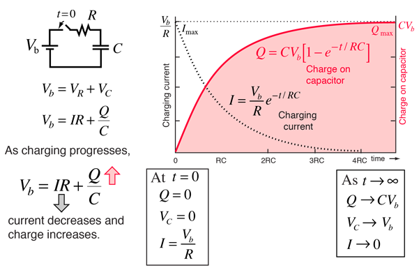
Capacitor charge graph and formulas by http://hyperphysics.phy-astr.gsu.edu
Therefore, if we are charging a discharged capacitor in an RC circuit containing a resistor with resistance \(R\) using a voltage source with voltage \(V_{source}\) and after \(t\) seconds the capacitor reaches \(V_{cap}\) then we can calculate the capacitance using the formula:
\(C=\frac{t}{R ln\frac{V_{source}}{V_{source}-V_{cap}}}\)If we charge with a micro-controller using a known resistor value and a known source voltage and while measuring time and voltage at the capacitor, then we can calculate the capacity of the capacitor. Keep reading for specific implementation on ATmega328 Arduino boards.
Please note that a capacitor in a RC circuit will fully charge (in theory) only after infinite time. For practical applications the convention is to consider the capacitor as fully charged after t=4RC seconds.
\(percentCharged(t)=\frac{V_{cap}}{V_{source}}=1-e^{-t/RC}\) \(percentChargedFully=percentCharged(4RC)=1-e^-4=98.16\%\)Building the sensor
Materials
To build such a sensor yourself you will need:
- A sheet of paper (A4, legal or letter)
- Matching sheet protector
- Aluminum foil such as the one used in the kitchen
- Sticky tape
- Two paperclips
- and Some wiring (preferably male to female “Dupont” jumper wires)

Step 1: Cut a piece of foil such that it is the same length as the sheet of paper but narrower than the sheet of paper creating some margins (~1cm).
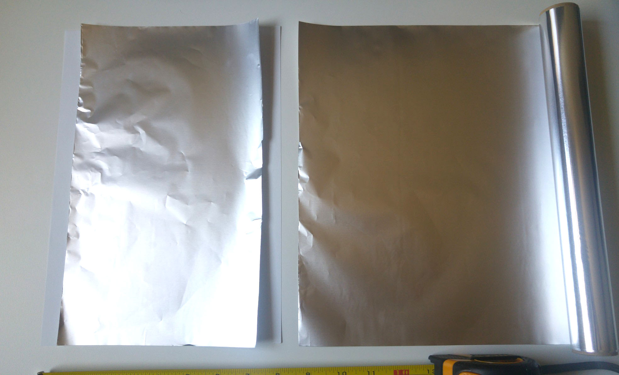
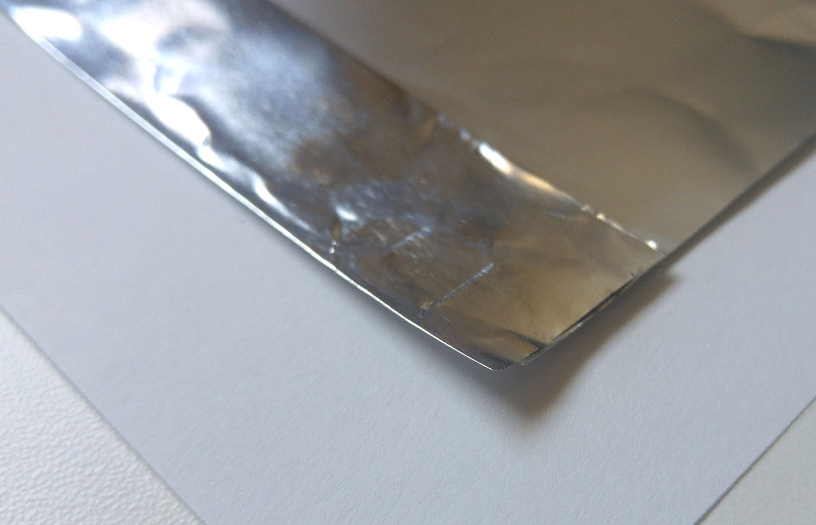
Step 2: Fold one short end of the foil a little bit twice to create a firm “lip” and at the same time shorten the foil so you have margins on the short ends as well.
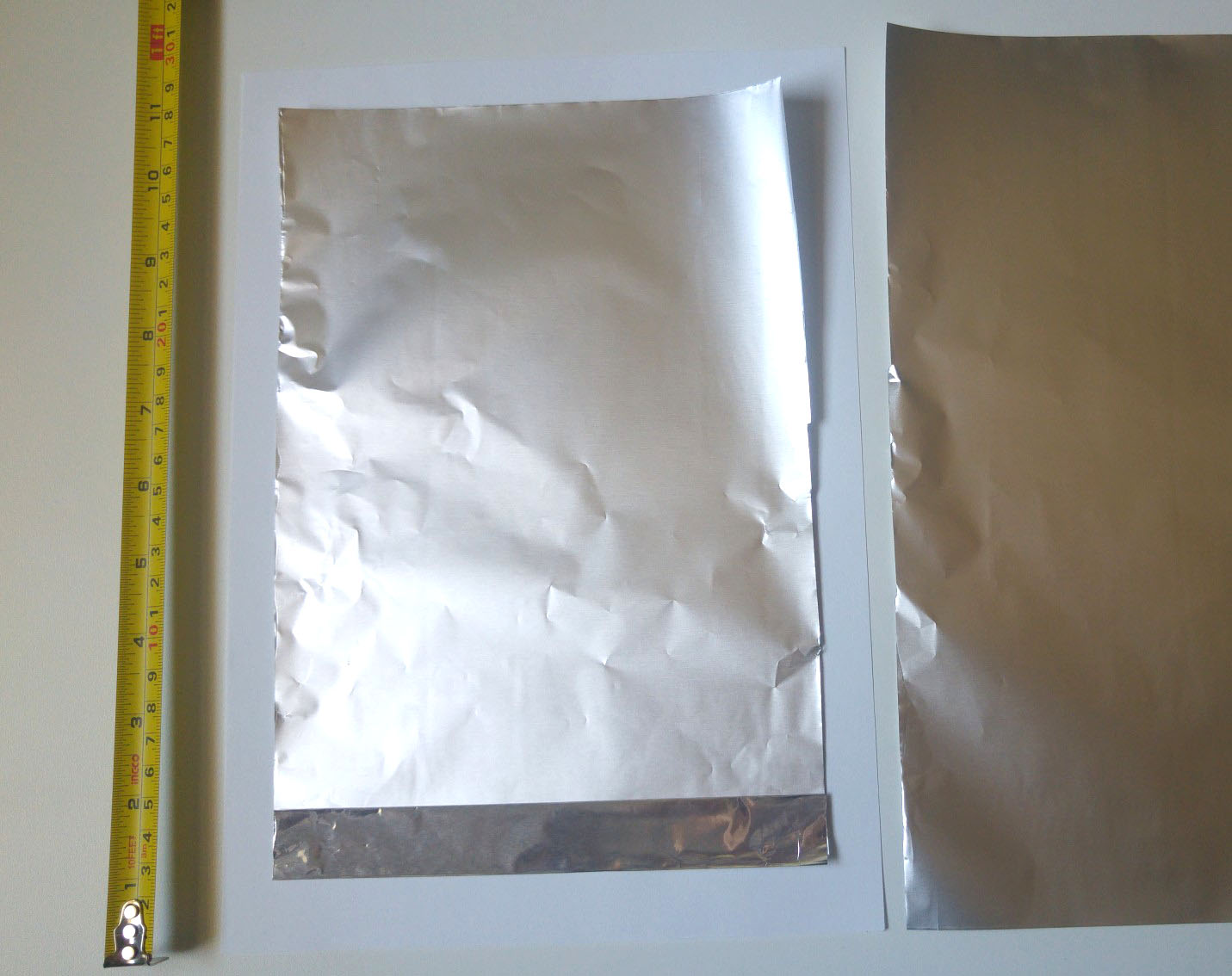
Step 3: Tape the foil to the paper on 3 sides except the the side with the fold.

Step 4: Repeat on the other side. 😉
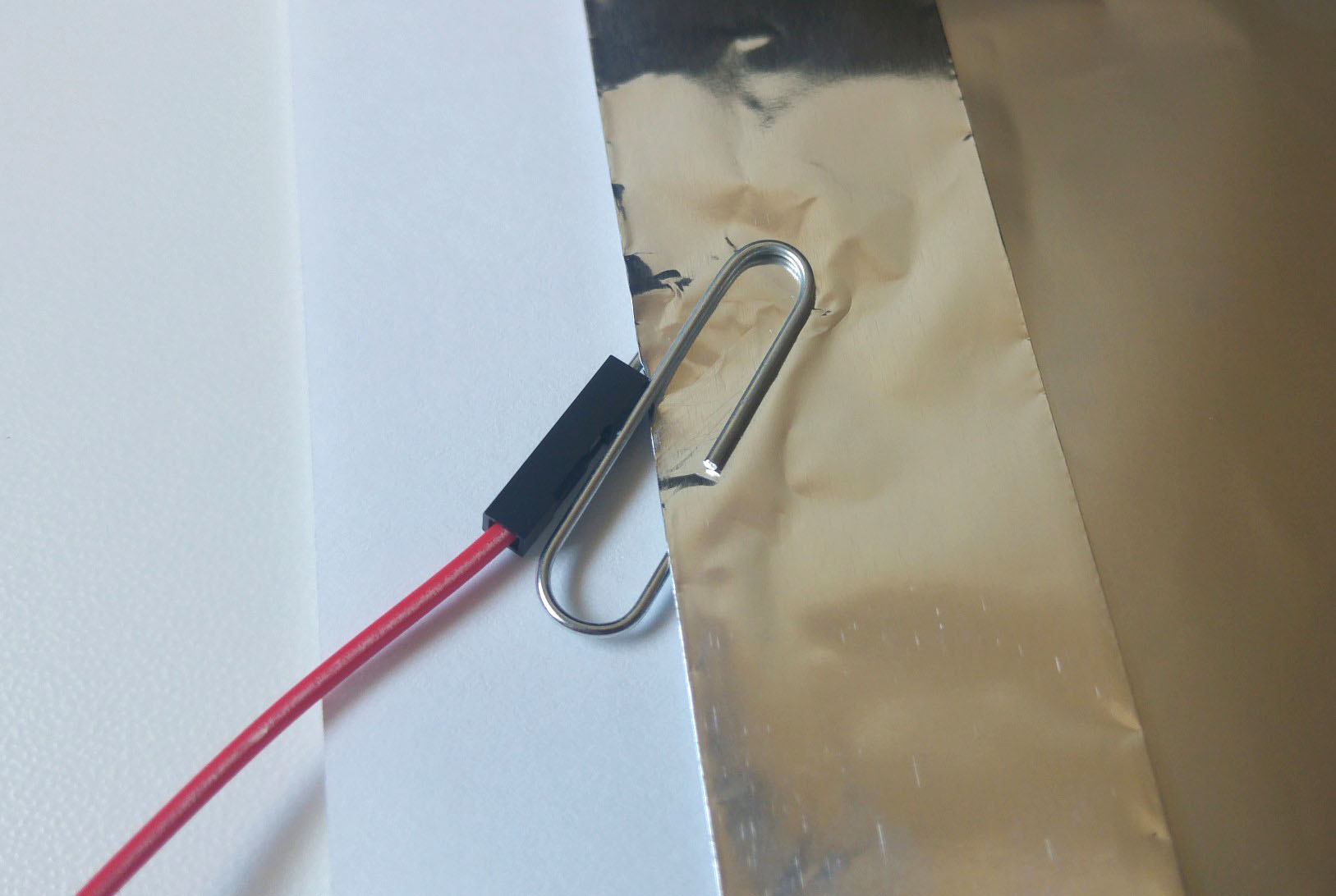
Step 5: Using the paper clips, connect one wire to each aluminum sheet. The fold provides a stronger mechanical point for a connection. If you prefer you can solder a wire to the paper clip instead of using jumper wires.
Step 6: Put the assembly in the sheet protector. Make sure the two conductive sides are not touching each other anywhere.
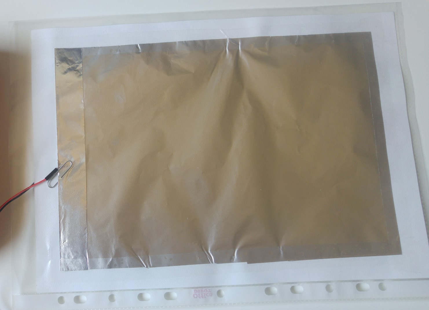
You are done!
Naturally you can make this is various sizes. Make sure to tape the foil only around the perimeter and keep it “loose” in the center. The “give” is what allows it to compress and expand when the sensor is used.
For best results, the positively charged side (red wire) should be facing any elements, which can capacitively affect the sensor, such as humans. For example, when using in a seat, the red side should be facing up.
Testing the result
A great quick way to test your creation is to use a DMM with capacitance measurement function.
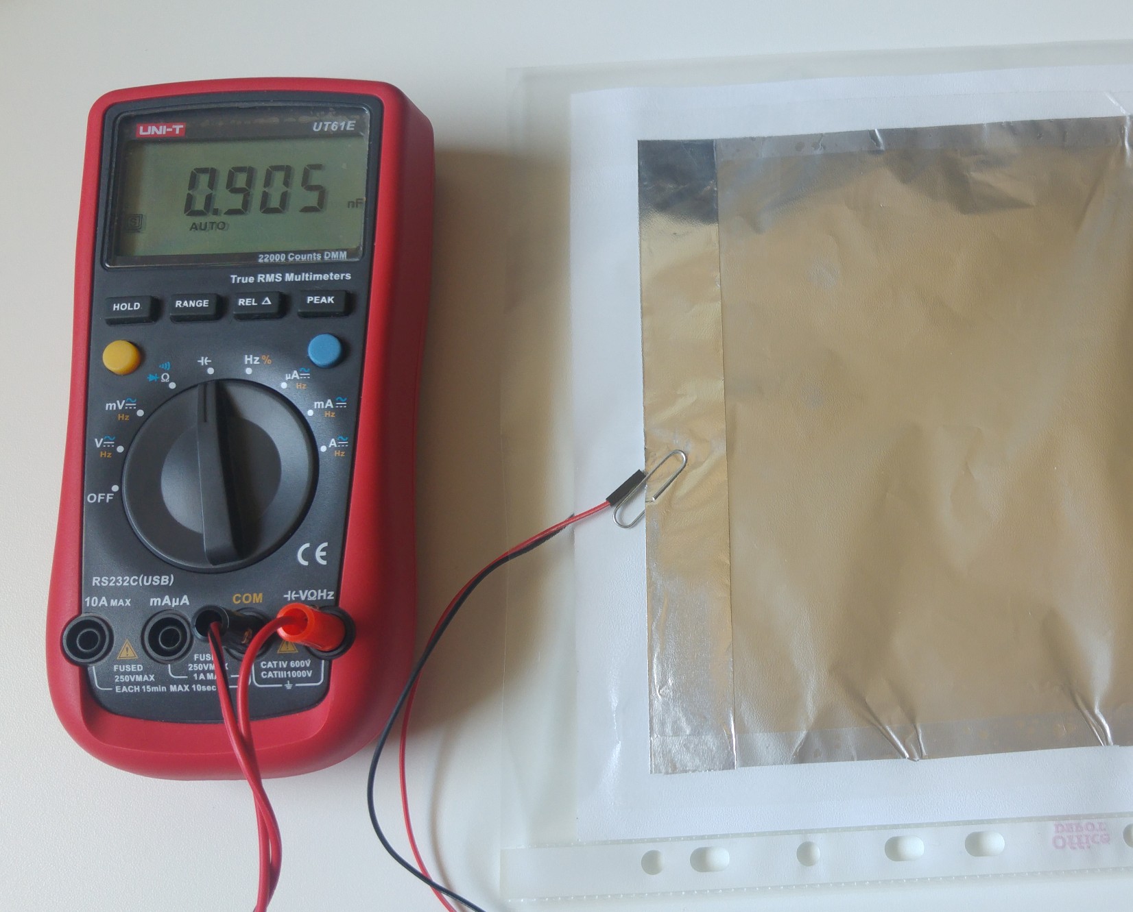
Measuring the capacitance of the sensor in idle state
We get a value of 0.9nF. However, this value also includes any capacitance in the wires and the meter. If we use the REL (relative) function of the meter to establish a baseline, we get a smaller reading:
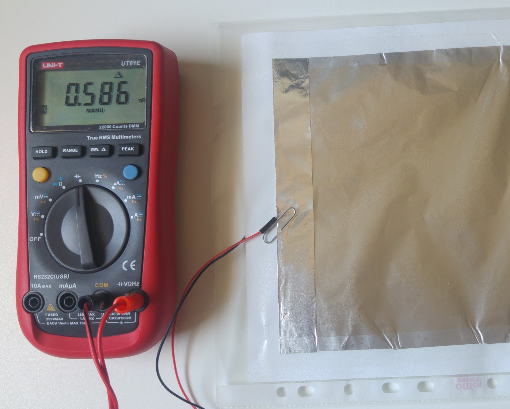
Measuring the capacitance of the sensor in idle state with REL function on
So the capacitance of the sensor itself, in idle state, is closer to 0.5nF.
Applying some force on the sensor increases the capacitance, as expected:
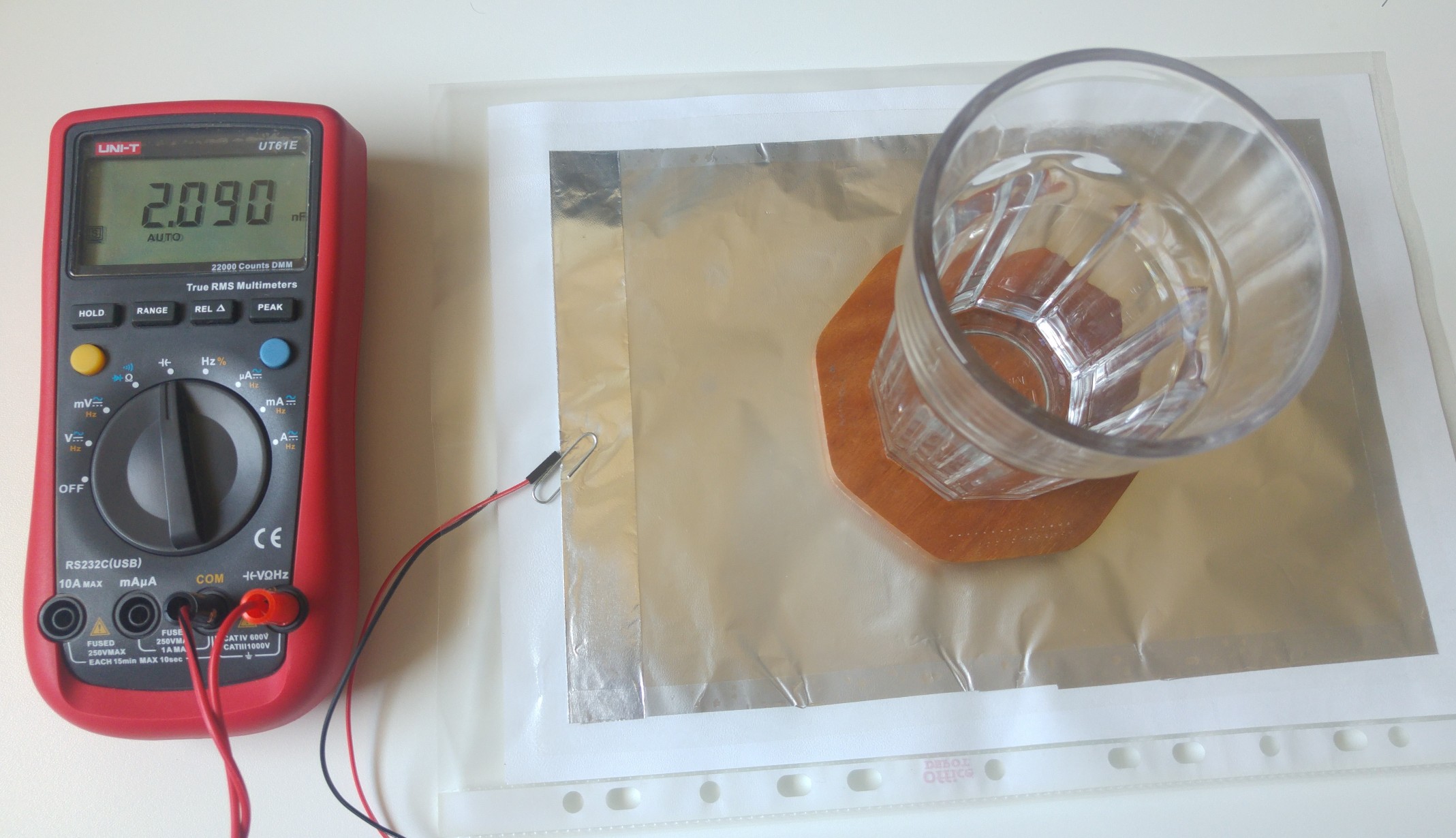
Measuring the capacitance of the sensor in “active” state
We get a stable reading of about 2nF that is about twice than the idle value. This stability will later make it easy to determine various states based on sensor’s reading.
Cost analysis
As you have noted by now, the sensor is incredibly simple and is made of common materials, mainly office and kitchen supplies. You probably have them already or know where to find them at no cost. Still, it would be an amusing exercise to calculate the BOM for this built. Here it is:
| Material/Part name | Package description | Note | Cost of package [USD] | Percent of package needed for unit | Cost of material for 1 unit [USD] |
|---|---|---|---|---|---|
| Dielectric material | A4 paper 500p 80gr | ~ 21 x 30 cm | $5.00 | 0.20% | $0.01 |
| Insulating package | Poly sheet protectors 100p, economy weight | To match paper size | $7.00 | 1.00% | $0.07 |
| Conductive plates | Heavy Duty Aluminum Foil 15m x 30cm | 14 micron or more | $4.00 | 2.67% | $0.11 |
| Glue | Sticky/Adhesive tape | 18mm width, 10m | $0.50 | 15.00% | $0.08 |
| Connector | Paper clips 100p 30-50mm | Without plastic, conductive | $1.00 | 2.00% | $0.02 |
| Connector + wire | 80PCS Dupont Wire Connector Cable Female to Male | 2.54mm 40cm | $4.20 | 2.50% | $0.11 |
| Total: | $21.70 | $0.39 |
An average cost of the materials is 40 cents. I have taken sample prices off the internet for the various components. The prices in your region might be different.
True, if you want to make one sensor and you have none of those materials then you will need to buy them in packages and the expense will be higher because it makes no sense to sell or buy one sheet of paper or one paper clip, but for most people this will not be the case in my opinion.
Implementing sensor sampling
Now that we have a working sensor, we need to read its value in our project rather than with a DMM. Some sensors provide a digital interface, which communicates over I2C or SPI protocols and is easy to use. Other sensors communicate their value by varying voltage or varying resistance, which is easy to read with an ADC. This sensor, however, communicates its value through its capacitance. Sure, we could find an IC (perhaps one coming from the world of capacitive touch sensing) that will let us do this. However, I decided to only use common and simple parts, so let’s build a simple, mostly software based, interface to measure capacitance and do it with my favorite open electronics framework, Arduino.
A trivial approach
There are many examples online for measuring the capacitance of a capacitor with an Arduino. In a trivial example we could use 3 pins and 2 resistors. Pin Pc will be used for charging through resistor Rc, pin Pd will be used for discharging through resistor Rd and analog pin Pm will be used for monitoring the voltage. Our capacitor has small capacitance around 1nF and will charge relatively quickly. To make this easy for us, let’s try to slow down charging as much as we can by using a high value resistor. If Rc will be 10MΩ, which is high but still widely available, then in this scenario, charging will take:
\(t=4RC=4*10M\Omega *1nF=40ms\)For discharge, we just want to do it as quickly as possible, but not too quickly so as not to damage the micro-controller. Per ATmega’s spec, 20mA should be safe so a good value for Rd would be:
\(R_d=\frac{V}{I}=\frac{5V}{20mA}=250\Omega\)with such a discharge resistor in place, discharging will be quite fast:
\(t=4RC=4*250\Omega*1nF=1\mu s\)The algorithm will include:
- Discharging: Setting pin Pd to OUTPUT LOW for a few micro seconds and then switching it to high impedance.
- Start of charging: Setting pin Pc to OUTPUT HIGH and noting the start time.
- Monitoring: Either waiting for a period of time that is shorter than the time we expect for the capacitor to charge (i.e. 20ms), or to sample the voltage using analogReads on pin Pm until we reach some desired value.
- End of charging: Reading the voltage on the capacitor and noting the end time. Setting pin Pc to high impedance.
- Result: Calculating C based on the formula by using all the constants and variables we have measured.
This method is best suited when you want to measure a value of a single capacitor, do that accurately and you don’t have to be very time efficient.
Optimizations
Preferably we would want to:
- Take the measurement much quicker, so we save time for other logic in our application or so we can sample the sensor frequently.
- Use less parts (resistors).
- Use more common resistor values.
- Use less pins.
In exchange, we are willing to lose some of the accuracy. We don’t have to know the exact C value, all we want is some value that is relative to the force applied to the sensor. If we can get some value a*C where “a” is some constant, then this value will be proportional to the capacitance, which will be related to the force and that would satisfy our requirements.
The first hurdle trying to optimize this process is that analogRead itself takes 0.1ms to complete. For our charging duration to be at the scale of hundreds of micro seconds or less, then by the time analogRead returns with the first reading, the capacitor would already had been completely charged and the reading becomes irrelevant. To reach micro second timings I decided to dump analogRead all together, and use digitalRead which takes 5µs. Unfortunately digitalRead doesn’t tell us the voltage at the pin, it only tells us if the value is “HIGH”. What is HIGH? Well, there is no specific value.
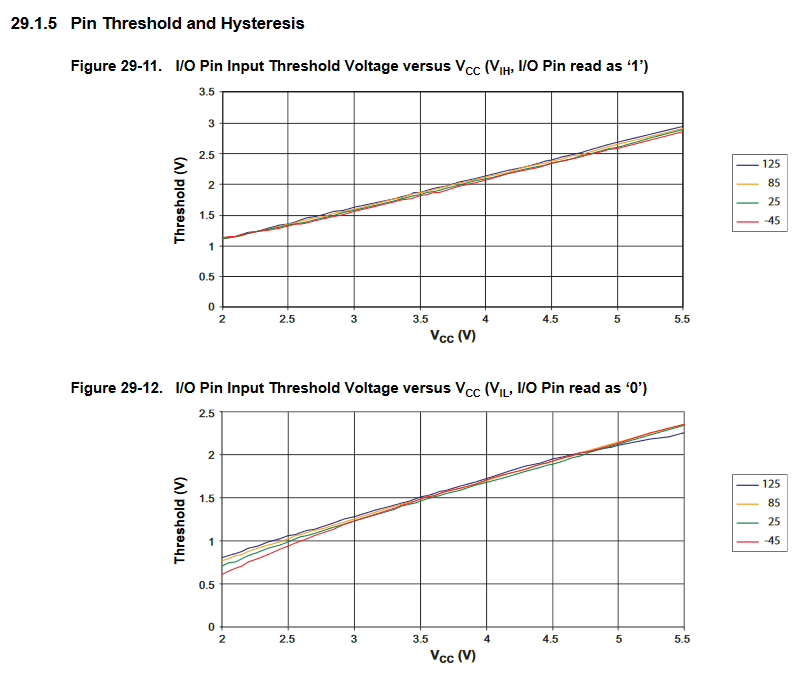
Section 28.2 “DC Characteristics” of the ATmega328P datasheet states that 0.6Vcc is the lowest value where the pin is guaranteed to be read as high, and 0.3Vcc is the highest value where the pin is guaranteed to be read as low. Those are safe, guaranteed values and there is a range in between that is not defined as it is common for digital logic. Actual threshold values will depend on Vcc, temperature and perhaps other factors. Section 29.1.5 “Pin Threshold and Hysteresis” of the datasheet suggests HIGH threshold value of around 2.6V for Vcc=5V and LOW threshold value of around 2.1V for Vcc=5V.
We now have a quick way of determining if the capacitor reaches the voltage of about 2.6V by using a digital read. Timing this event will give us the measurements necessary to calculate the capacitance. As a next stage, I replaced digitalRead with direct PORT register access by pre-calculating some variables using: digitalPinToBitMask, portInputRegister and digitalPinToPort. This reduced the (in-loop) time to read the pin once to just 1µs!
The second hurdle is reducing the complexity of the circuit by eliminating non-critical components. As described by Jonathan and suggested by Scott in a comment at Hackaday, you can use the built-in pull-up resistor of the ATmega to charge the capacitor. Section 28.2 “DC Characteristics” of the datasheet defines the I/O pin pull-up resistor as having a value between 20 and 50 kΩ. Quite a range, but it is typically around 40kΩ. As I already mentioned, we don’t care if there is a ratio involved, as long as it is fixed per device/pin, which it is. Using the pull-up has the additional advantage of freeing a micro-controller pin because we can use the same pin for monitoring the voltage and charging at the same time (using the INPUT_PULLUP mode)!
The third hurdle is simplifying discharge. Unfortunately, the ATmega doesn’t have a pull-down resistor built in. I have seen some implementations, where the capacitor is discharged by connecting it to a LOW pin without a resistor. I was not able to find evidence that this is safe for the micro-controller. Clearly there is some built-in resistance inside, but if resistance is too low, then the initial current can be too high for the device. LMK in the comments if you have any information on this topic. I decided to keep a resistor for the discharging step, but found a way to eliminate the need for a discharge pin. It works like this: I am using a discharge resistor that is always there, so the capacitor is always discharging. When charging, it is charged at a higher rate then its default discharge rate, so we can achieve both discharge, charge and monitoring with a single digital pin! The downside is that discharging now takes on the order of magnitude of a milli-second rather than micro-seconds. This is ok for my application, but if you want to sample the sensor at a high frequency, this optimization might not be suitable for you.
What values can we use for the discharge resistor? The next section has some math. If you are not comfortable with math, you can skip the calculations and jump straight to the point where a resistor is chosen. I decided to include the calculations instead of just throwing a value out there. Besides the process being potentially interesting, one may need to redo the calculations if they have different initial requirements, such as different micro-processor architecture or a different range of capacitor values that needs to be measured.
The combination of a discharge resistor and a charge resistor at the same time creates a voltage divider, so the capacitor is now charged at less than Vcc. It is critical that we hit the HIGH threshold to stop the charging so we need to satisfy:
\(V_{source}=\frac{R_{dis}}{R_{dis}+R_{ch}}V_{cc}>V_{th}=0.6V_{cc}=V_{cap}\) \\
\(R_{dis}>0.6R_{dis}+0.6R_{ch}\) \\
\(R_{dis}>1.5R_{ch}=1.5*50K\Omega=75K\Omega\)Next, it takes us a few micro-seconds each time to sample the voltage. For us to have stable readings and eliminate noise it makes sense to spend a few orders of magnitude more on the charging process. If we aim to spend at least 100µs on charging a 1nF capacitor with the 50KΩ pull-up resistor we would need to charge the capacitor to:
\(t=100\mu s, RC=50K\Omega*1nF=50\mu s\) \\
\(percentCharged(t,RC)=1-e^{-t/RC}=86.46\%\)About 85% or more of the max charge. However, percent charged is also defined as:
\(percentCharged=\frac{V_{cap}}{V_{source}}\)and so we get another requirement
\(85\%<percentCharged=\frac{V_{cap}}{V_{source}}=\frac{V_{th}}{V_{ch}}=\frac{0.6V_{cc}}{\frac{R_{dis}}{R_{dis}+R_{ch}}V_{cc}}\) \\
\(85R_{dis}<60R_{dis}+60R_{ch}\) \\
\(R_{dis}<2.4R_{ch}=2.4*50K\Omega=120K\Omega\)Combining the two requirements we get:
\(75K\Omega<R_{dis}<120K\Omega\)I ended up using a 100kΩ discharge resistor, which satisfied the requirements and is a very common value.
It is worth noting that an assumptions of \(R_{ch}=50K\Omega\) and \(V_{th}=0.6V_{cc}\) in the second part are not accurate since the pull-up can be between 20 and 50 kΩ while actual HIGH threshold is around 2.6V, but it is fine in practice because we are trying to hit a specific order of magnitude rather than an exact length of time.
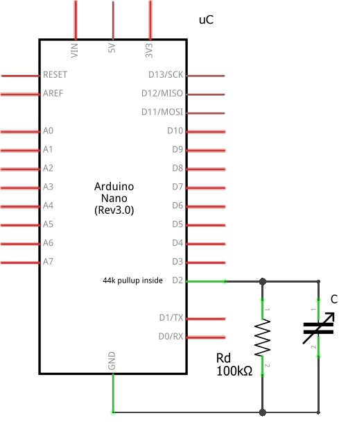
Circuit
Our sensor interface circuit is now composed of one 100KΩ resistor and uses one digital pin on the micro-controller.
Code
Here is an example code that can measure the value. The example is based on the production sensor code from the Fochica project.
/*
Capacitive pressure sensor interface - https://blog.yavilevich.com/
Copyright (c) 2017, AY Garage Ltd. All rights reserved.
This program is free software: you can redistribute it and/or modify it under the terms of the GNU General Public License as published by the Free Software Foundation, either version 3 of the License, or (at your option) any later version.
This program is distributed in the hope that it will be useful, but WITHOUT ANY WARRANTY; without even the implied warranty of MERCHANTABILITY or FITNESS FOR A PARTICULAR PURPOSE. See the GNU General Public License for more details.
You should have received a copy of the GNU General Public License along with this program. If not, see &amp;amp;lt;http://www.gnu.org/licenses/&amp;amp;gt;.
*/
#define TIMEOUT_ATTEMPTS 1000 // how many rounds to do in the loop before deciding to timeout
#define DISCHARGE_FACTOR 4 // how much discharging is slower than charging
int readSensor(uint8_t senseAndChargePin)
{
// pin registers
// do this once at setup - https://forum.arduino.cc/index.php?topic=337578.0
uint8_t myPin_mask = digitalPinToBitMask(senseAndChargePin);
volatile uint8_t *myPin_port = portInputRegister(digitalPinToPort(senseAndChargePin));
// Start charging the capacitor with the internal pullup
int left = TIMEOUT_ATTEMPTS;
noInterrupts();
pinMode(senseAndChargePin, INPUT_PULLUP);
// Charge to a HIGH level, somewhere between 2.6V (practice) and 3V (guaranteed)
// Best not to use analogRead() here because it's not really quick enough
// Want to do as little as possible in this loop to get good resolution
do
{
left--;
} while (((*myPin_port & myPin_mask) == 0) && left>0); // An iteration takes approximately 1us
interrupts();
pinMode(senseAndChargePin, INPUT); //Stop charging
int roundsMade = TIMEOUT_ATTEMPTS - left;
// Discharge is slower than charge, typically goes through a 100K resistor where charge is a ~40K resistor
// Charge time is approximately "roundsMade" micro-seconds, so use that approximation for discharge delay as well
delayMicroseconds(roundsMade * DISCHARGE_FACTOR);
return roundsMade;
}
A few observations and notes:
- We sample the pin as fast as possible doing as little operations as possible in the loop.
- We disable interrupts for the duration of the measurement to reduce side effects.
- We don’t actually measure time, instead we measure the number of loop iterations until the pin is HIGH.
- There is a configurable timeout logic, so we are not stuck in an endless loop if nothing is connected.
Let’s take another look at the formula of capacitance:
\(C=\frac{t}{R ln\frac{V_{source}}{V_{source}-V_{cap}}}\)In our process, the resistor value and voltages are fixed and the number of loop iterations is proportional to the time spent. As a result, the number of iterations is proportional to the capacitance. With a simple calibration it is possible to calculate the coefficient for calculating the capacitance, but as I have mentioned, in this application it doesn’t matter as we are going to “correlate” the number of iterations to the pressure directly, without going through other properties.
Using the sensor as binary sensor in practice
In many applications we are interested to know a binary state, on/off, occupied/empty, idle/active, etc. This sensor and its implementation, on the other hand, provide a integer range, which can span between 0 and 500 (or more). The whole process of measuring the response for each state and mapping the responses to states will be referred here as calibration. It should be noted that the way the sensor is built, where and how it is installed, and what kind of pressure is applied to it, can lead to differences in the relevant ranges of the same state on different instances. Therefore we might not get the expected result if we trivially map the responses to binary with fixed threshold values, hence the importance of calibration.
The first step to get a binary result would be to identify what values are typical for each state. We can do that manually by generating the states and measuring the response, but in some applications this can be done automatically. For example, typical applications of touch buttons can calibrate automatically by making two assumptions. First, that at initialization time the state is known (off) and second, that touches (on) are quick. Based on this data, the controller can keep a baseline of what represents an “off” state and when a significant deviation is detected it would determine that an “on” state has occurred.
Once you have determined the values for each state, you have to decide how to map the entire ranges of values to these states. A trivial approach would be to set a single threshold that is in the middle between the two states. However, that can often generate unstable on/off switching if the signal oscillates around the threshold due to noise or an inaccurate reading. A popular approach is to use a Schmitt trigger, which is a dual threshold scheme which can be implemented in hardware or software. Each state has a separate threshold, which the signal needs to cross in order to switch to that state. Once switched, it is not enough to cross the same threshold back again, the signal needs to cross the threshold of the second state, which can be set such that mere noise or slight variations are not enough to trigger the change. Such a scheme, with properly defined thresholds, provides a robust and stable binary response. With some work this can even be adapted to applications with more than 2 states in the range.
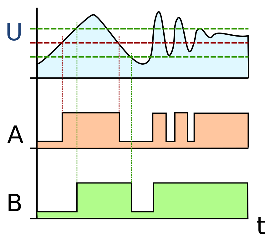
Comparison of the action of a single threshold comparator A and a dual threshold Schmitt trigger B. Source: Wikipedia, CC-Attribution-ShareAlike, https://en.wikipedia.org/wiki/File:Smitt_hysteresis_graph.svg
What next?
Hoping that others will experiment with this design, find it useful and improve it.
Looking forward to getting feedback and suggestion. Enjoy!
This is awesome! Well written article, ready to follow and great inspiration. I am actually working on shields for combat robots which register BB gun impacts and I’ll rethink the whole design based on your method. Your baby car seat alert project is also awesome, the idea of forgetting your kid in the car is dreadful and sadly, it probably can happen to anyone…
Hi Michel,
Thanks for your feedback.
Registering a BB gun impact sounds challenging. I assume it is a small and quick event which is difficult to sense. LMK how it goes. Perhaps you should try a faster MCU for this task. I got good results with an ESP32.
Good luck!
You’re right, I remembered afterwards that I used the vibration which lasts longer (through a low-pass amplifier) to detect impacts with a MEAS LDT0 sensor. The signal is then registered by a PIC which doesn’t have to be particularly fast.
Still, I love your idea. It would be fun to have shields sensitive to impacts and not to vibration. I’ll let you know if I end up doing it!
Hi Arik
Wow nice. Have you done any more with this?
I am interested in a similar application to monitor transient pressure in a bottle. The measurement device would be in the cap. In my case there would be a signal transmitted by bluetooth to a mobile device. Any thoughts on that application? Pressure fluctuations would be small to moderate. Less than 5 psi.
Hi Dr,
A cap is quite small. I think this design works best when the sensing area is large.
Check this project: https://hackaday.io/project/7077-no-battery-nfc-air-pressure-sensor might be relevant.
Hi, Would this work for your project
https://www.digikey.com/product-detail/en/cypress-semiconductor-corp/CY8CKIT-145-40XX/428-3807-ND/6194774
Regards,
Seamus
Hi Seamus,
Probably, but why pay for something when you can do the same functionality for free (or less).
Hi Arik, I meant that one could do all the development on the CY8CKIT which
has microcontroler, amplifier, etc ) and use the capsense function built in already. Seamus
This is awesome! Well written article, ready to follow and great inspiration.
Hi,
Great project!
Note classical electronics considers a capacitor t be fully charged after 5 time constants or T=5rc.
Did you consider using metallized plastic film for your sensor? A great source is potato chip bags!
Cheers,
Paul
Hi Paul,
In the end 5RC or 4RC doesn’t really matter. I am not trying to charge it fully, just to the point where it is detected as a ‘1’ digital value.
Regarding metallized plastic film, didn’t consider that. Interesting. What do you think would be the advantages of using that vs aluminum foil?
Hi Arik,
Really nice project.
Can we convert the reading to weight units – g, kg etc?
Thanks.
Hi Alex,
Probably not, but you can try. Put some weights and calibrate.
I think the readings are more of a ballpark value good for yes/no indication.
Hi Arik,
your project is great. I’m trying to adapt the capacitor layout (from parallel to coplanar) to measure the water content of soil. Do you think could it work?
thanks
Paolo
Hi paolo,
The electronic part doesn’t care what type of a capacitor that it. It will measure the capacitance. So it should work for you. Mind that I am not familiar with co-planar capacitors or measuring water content in soil.
Hi Arik! Thank you for this awesome idea! I am a teacher trying to make this a project for my middle school science classes. Would you be able to share photo or video of how you connect the wiring to the paper clip and how to connect the wires to the multimeter? I am a beginner at this stuff and am trying to figure it all out. Thanks I’m advance!
Hi Ahsley,
The clip is connected to a female dupont-style jumper wire. You can see it in this image: https://blog.yavilevich.com/wp-content/uploads/2017/10/Sensor-connector.jpg
In other occasions when I needed something more robust I have also soldered the wire to the clip.
The multi-meter has cables with alligator clips on the other end. That grabs the other end of the jumper wire. Some examples would be: https://www.amazon.com/alligator-clips-multimeter/s?k=alligator+clips+for+multimeter
Interesting stuff, and understandable, even for me.
What i am wondering, though, is what if I’d want multiple of these sensors, and therefore there is a difference in the length of the line going to the digital pins of the arduino?
Would it be required to seperate the 5v needed for charging, from the 5v going to / from the digital pin?
My use case would be to put one of these on every stair of a staircase, to see on which one a person is standing, but would like to ‘feel’ across the whole of the stair, so think an fsr is out.
Hi Frank,
You would need one such sensor per stair and one digital pin per stair. If your MCU can’t do PULLDOWNs then you will also need a resistor per stair.
You shouldn’t worry about the length of the line.
You don’t need to separate the 5v needed for charging, from the 5v going to / from the digital pin.
Arik, thanks for the quick reply.
Since the MCU would be an Arduino MEGA, I think pulldown resistors are indeed required. If I understood internet right, this means I get 5v supply to capacitor, capacitor to digital pin and capacitor to resistor to ground.
Then there seems to be a trade-off between impact sensitivity and energy consumption. I need to choose the resistance such that when the sensor is not pressed, it is (just) below logical low voltage, this would ensure that logical high is reached the soonest and power consumption the lowest.
I think I understand the charging thing. Read about that in 5V LED strips, but I guess the power consumption of a capacitor is minimal compared to a LED.
I guess you didn’t need any pull-downs, because you were reading only one sensor and thus the state being indicated by it, is the state you were interested in. Or would a pulldown in your use case have been ‘cleaner’ as well?
This whole process would work the same, if I were to use some sort of shift register, as its pins would be, in effect, replacing the digital in pins. (Considering this, because, I’d like to do more tinkering, and I see potential for combination with other things for which I would need digital in/out pins, such as a light sensor, and potentially something to log the stair case usage.)
Any thoughts on circuitry to measure only the first and last two stairs, and when those are pressed, the others as well, in order to limit energy consumption further? (Or would that be overkill in terms of energy efficiency?)
Hi Frank,
“Since the MCU would be an Arduino MEGA, I think pulldown resistors are indeed required.”
Correct.
“If I understood internet right, this means I get 5v supply to capacitor, capacitor to digital pin and capacitor to resistor to ground.”
Are you referring to the schematic in the article or to something else?
“Then there seems to be a trade-off between impact sensitivity and energy consumption.”
Possibly. Are you going to be operating this from a battery? This isn’t optimized for battery operation but rather for having power from mains as needed.
“I need to choose the resistance such that when the sensor is not pressed, it is (just) below logical low voltage, this would ensure that logical high is reached the soonest and power consumption the lowest.”
When the sensor is not being measured (not related to it being pressed) it has no charge and voltage will be 0V. I feel that you are confused about how this design works.
“I think I understand the charging thing. Read about that in 5V LED strips, but I guess the power consumption of a capacitor is minimal compared to a LED.”
A DC capacitor mainly consumes power when it is charged or discharged and a very small charge due to leakage.
“I guess you didn’t need any pull-downs, because you were reading only one sensor and thus the state being indicated by it, is the state you were interested in. Or would a pulldown in your use case have been ‘cleaner’ as well?”
No. I didn’t need pull-downs when I was using an MCU that has pull-down capability, such as an ESP32.
“This whole process would work the same, if I were to use some sort of shift register, as its pins would be, in effect, replacing the digital in pins. (Considering this, because, I’d like to do more tinkering, and I see potential for combination with other things for which I would need digital in/out pins, such as a light sensor, and potentially something to log the stair case usage.)”
I might not be possible to use a SR as the pins here are used for reading and not just sending a signal. Perhaps some kind of multiplexer will work. I didn’t try.
“Any thoughts on circuitry to measure only the first and last two stairs, and when those are pressed, the others as well, in order to limit energy consumption further? (Or would that be overkill in terms of energy efficiency?)”
Sure, you can do that.
Many thanks, slowly starting to get it, I guess
Hey, I have a small question, what is the relaxation time of these paper type dielectric material capacitor? I am trying to make similar sensor, however, after releasing the pressure, the capacitance comes back to original value in 1 to 2 seconds.. which is alot in my case. Can you suggest what kind of dielectric can solve this issue to have relaxation time of 1ms max?
Hi Ismail,
1 to 2 seconds seems right to me for this sensor.
Don’t know what to suggest for such a quick detection. Even a mechanical button need 10-20 ms to switch states.
Wow, this DIY pressure sensor project is a true testament to the wonders of creativity and innovation! Building a capacitive pressure sensor at such a low cost is truly impressive. The step-by-step guide and the use of easily accessible components make it an attractive project for DIY enthusiasts. Kudos to the author for sharing this budget-friendly and educational project. Let’s keep exploring the world of DIY electronics and learning through hands-on experiences!