
This is a quick follow-up post to my previous article about converting a Rinnai heater device to a smart device and controlling it with WiFi. Previously, when making the board that connects between the ESP32 and the traces of the Rinnai control panel, I did something that is not per-spec. I was using the ESP32 to sink 5V to ground. Sure it is only around 0.45mA of current but still, lets fix it.
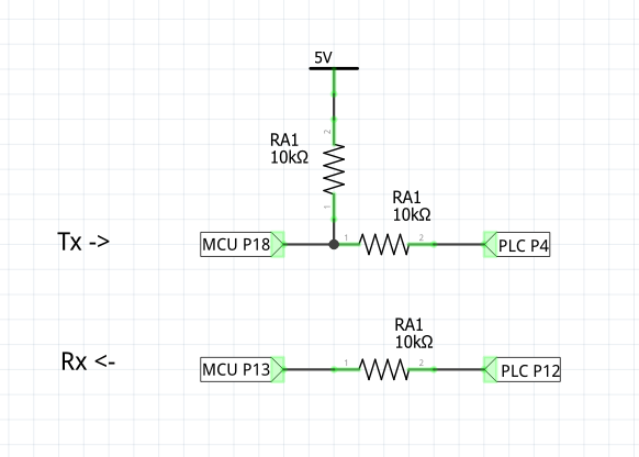
To recap, the original circuit for MCU to PLC communication looks like this:
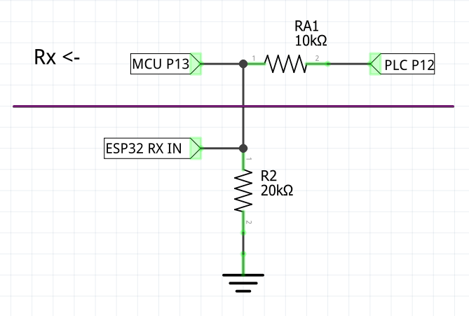
I have already solved the RX part by adding a 20Kohm resistor to ground to drop the voltage levels from 5V to 3.3V. This part remains as-is:
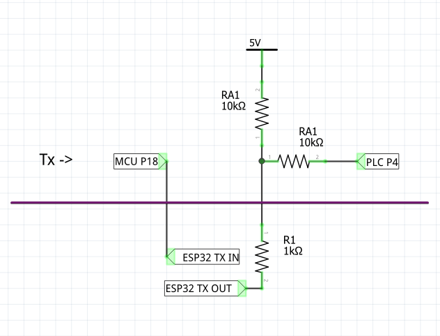
The rev1 TX part was:
The new TX part is just going to have an extra N-CH MOSFET:
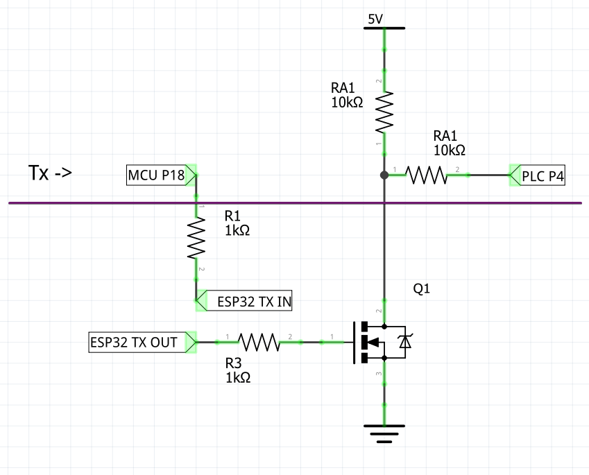
Note that an N channel MOSFET in this configuration inverts the signal. Meaning that when “ESP32 TX OUT” is LOW then PLC P4 is HIGH. Typical logic level converters are not inverting, but they implement a more complex circuit with additional resistors to accomplish that. Since we already have resistors on the traces inside the panel that would cause the voltage to drop, so this logic will not work. It is easier to pre-invert the signal at the source in software than to add additional components. This is exactly what I had done here. See TX_OUT_INVERT parameter. Advantages of open source!
Next I made a perfboard design in Fritzing:
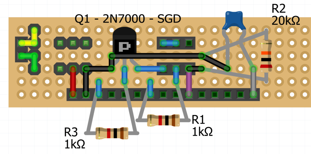
I had 2N7000 MOSFETs around so I decided to use them. Pin order is S-G-D. It is a N-channel MOSFET despite what the representation in Fritzing shows. You can use other models, but make sure they will close fully with 3.3V at the gate.
As before, the capacitor on the EN pin of the ESP32 helps it boot into programming mode. This might be specific to the ESP32 module I used and might not be needed in other cases. The yellow/green connector on the left is just for connecting the cable of the panel to the cable of the main unit. The connectors at the top are for “parking” the cables and entering legacy or bypass mode.
Note that it is invalid to connect ESP32 IO pins to a source and the ESP32 to Gnd without also connecting Vcc. This is invalid because IO pin ranges are defined relative to Vcc and it is dangerous because the ESP32 will try to power up through the IO pins. So always disconnect the 3 pin power connector if you are going to remove the ESP32 or disconnect Vcc, otherwise it will cause voltage drops on the data lines and things will stop working. Even better, power down the entire system before connecting or disconnecting any wires. If you are having difficulties, you can move the data connector to the parking spot to enter bypass mode and essentially “roll back”.
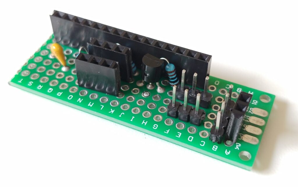
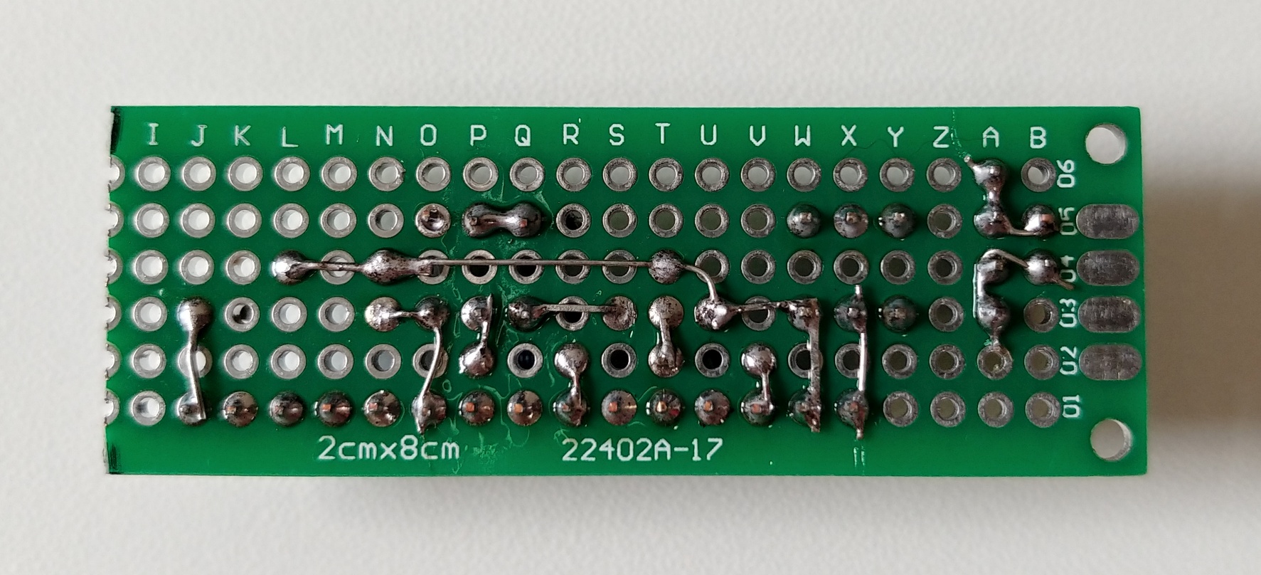
Satisfied with the design I implemented the board:
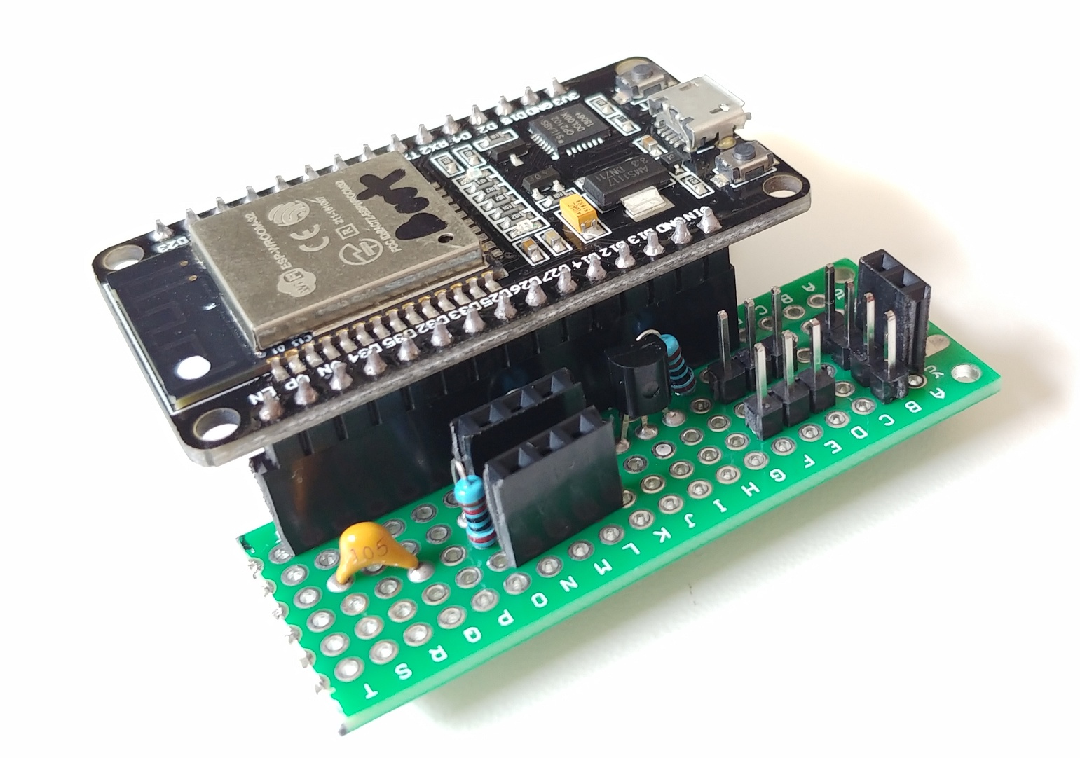
As before, I used a mockup of a Rinnai system to test the new board before a “production” installation:
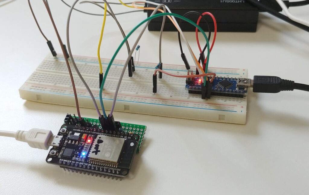
The Nano is emulating the original control panel by generating fake inputs for the board. Inputs and outputs are being captured by a logic analyzer -> Sigrok -> PulseView -> rinnai-control-panel-sigrok-pd (LSPR?!) pipeline.
Now is the time to connect our new rev2 brains to the control panel and make some automations in Home Assistant. 🖖
How did it work for you? I have a Rinnai and am looking at doing this. I have the WIFI controller but it is integrated with smarthings and my hub goes belly up at the end of the month. So I am setting up HA on a old Dell Optiplex 7040 MFF with a NORTEK HUSBZB-1 Zwave Zigbee USB adapter. I am leaving smarthings coming from a HUBv1 but almost my entire house is automated.
Hi Daniel, works great.
Wi-fi reception in the installation point was so so. Had some packet/ping loss and delays in response. Change to an ESP32 board with an external antenna. I recommend this unless you already have good Wi-fi reception at the installation point.
Spent some time troubleshooting something I thought was a bug where the unit will not turn on. It turned out to be just a safety mechanism in the Rinnai where it wouldn’t let you turn the unit on if there is water flowing. So take that into account, you can’t turn it on if someone is using hot water at the same time.