Lately I am working a lot with Arduino, which is a new field for me, hence fewer posts. Arduino is a very popular entry level embedded electronics platform. My latest Arduino project features Bluetooth Low Energy (BLE) communication. Arduino boards have no built-in BLE capabilities so I was looking to add a BLE module to my circuit. After some research, the name HM-10 comes up as a popular and simple BLE option for Arduino. I ordered an HM-10 BLE module from the Far East via ebay. I soon discovered that there are many complexities involved, even before you get to send or receive the first packet over the air. The difficulties originate from the existence of “clones” of the original module, that though sold as HM-10 are actually different in some aspects from the original. Eventually I ordered and worked with both the original and clone. In this article I will cover the basic construction of the modules, the differences and will present an Arduino sketch that can automatically identify which module you have and then help you configure it without needing to remember the commands.
Parts of an Arduino BLE module
HM-10 Front
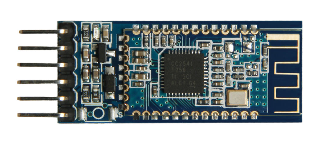
BLE system-on-chip (SoC) and micro-controller unit (MCU)
All the BLE modules I have seen use the Texas Instruments (TI) CC2541 chip. This is the large black square in the middle of the module as can be seen in the photo above. Online resources suggest that the CC2540 chip, that is similar, can also be used. This chip is programmed with matching firmware and it then implements the logical layers needed for the BLE protocol. The chip operates at voltages between 2V and 3.6V.
Daughter board
This is the light blue part in the photo above. The CC2541 chip needs some passive components to work, such as oscillators, capacitors, resistors and an antenna. Those are provided by this board. The daughter board is soldered to the main board around the perimeter, via arc-like soldering pins.
The daughter board that you can see in the photo above is the HM-10 module, made by Chinese “JNHuaMao Technology Company”, hence the HM initials. Their site is www.jnhuamao.cn (It might have been hacked at some point, so it is showing a “Reported attack page” warning for me in Firefox. Proceed at your own risk). JNHuaMao makes different kinds of Bluetooth modules. In this case they designed the board and wrote a firmware for the TI chip to implement the needed functionality. The firmware determines the interface that will be used to control the module over serial connection.
Another Chinese company, “Bolutek Technology Co., Ltd“, decided to make a similar board. Their model is called CC41-A (CC41 from now on). It uses the same TI chip and similar board design (both are based on TI’s reference design for the chip). One difference that is easy to spot is that CC41 only has one oscillator where HM-10 has two. This is ok as one of the oscillators is optional per CC2541 specifications. See a photo of the CC41 module below and identify the missing oscillator.
CC41 Front
As can be seen, the daughter boards are very similar. The pins are also compatible. Regardless of whether Bolutek copied the board design or made one of their own, many sellers were selling the CC41 module by using the HM-10 module name. This led to confusion and caused JNHuaMao to launch a campaign against clones posting various accusations. The bottom line is that these two daughter boards have the same TI chip, very similar board layout but different firmware. When ordering from the Far East, relying on model name alone, you might not know which exact model you will be getting.
Voltage-wise, the daughter boards have no voltage regulators and expect to be powered by 3.3V per chip specifications. Similarly, the serial logic expects 3.3V TTL levels.
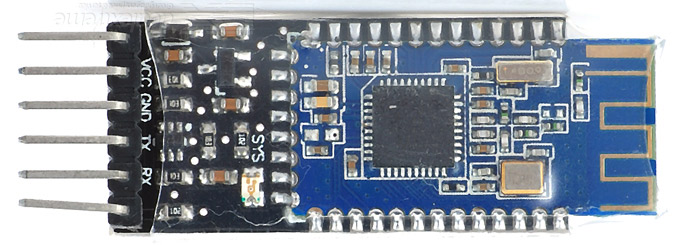
Module (breakout) board
These daughter board modules are not Arduino specific and expected to be soldered on to another PCB, for example one inside some remote controlled device. This is not convenient or popular in the Arduino space. Arduino modules are usually 5V and are connected with 2.54mm spaced pins which are good for solderless breadboards. This is where the breakout board comes in. The breakout board is the largest part in the photos above. It is the dark blue PCB with pins. The breakout board can add a voltage regulator to drop 5V to 3.3V, serial logic level conversion, leds, buttons and protection circuits.
A typical BLE module breakout board has between 4 and 6 pins. I would highly recommend getting the 6 pin versions. The basic pins are Vcc, Gnd, Rx and Tx. The additional pins depend on model and could be STATE, EN(able) or BRK. STATE allows you to know current module connection state, EN allows you to enable or disable the module and BRK allows you to initiate a disconnect of the current connection.
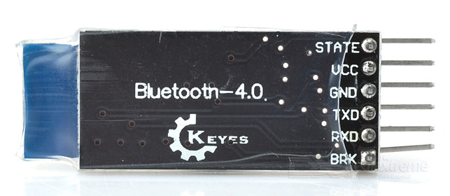
Keyes, HM-10 Back
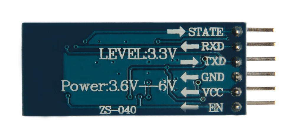
ZS-040, CC41 Back
There is no particular reason to have a two PCB hierarchy. In fact, a company could have made a single breakout board to take us from a chip directly to 5V breadboard pin form-factor. In reality, the breakout boards are typically made by completely different companies than the ones making the daughter modules. Adding some logic to adapt a circuit for Arduino is a much simpler task than writing a firmware for Bluetooth and different companies that target different markets specialize in each task. In the photos above you can see that Keyes made the breakout board for the HM-10 while the CC41 breakout board is marked with “ZS”.
Further differences can be seen in pin order, serial logic voltage levels and price. The more expensive Keyes HM-10 module has an on-board 5V to 3.3V logic level conversion on pins Rx and Tx. This allows direct connection to Arduino digital pins. On the other hand, the simple ZS, CC41 module is clearly marked “LEVEL: 3.3V” meaning some logic conversion needs to be done. You can use a logic conversion chip/module or you can make your own voltage divider with two resistors to drop voltage on Arduino’s Tx pin by 2/3 for it to work properly with CC2541’s Rx pin.
It should be noted that there are other types of breakout boards (AC-BT-V4) and other types of daughter boards (i.e. HC-08) than those mentioned in this article. The principle should remain the same though. If you have one of the other modules in your possession I am interested to learn more to improve this resource. Please reach out.
Communicating with the module
In this article I will be assuming that you are connected in the following way:
- A PC connected to the Arduino over a Serial connection through a USB port. Using the hardware Serial port(s) of the Arduino.
- The Arduino is connected to the BLE module via Serial Rx and Tx pins (and power, obviously). With logic conversion, if required by the module. Using SoftwareSerial on any two available Arduino digital pins.
- The BLE module can then be connecting wirelessly via RF to another BLE device.
Both the HM-10 and CC41 use AT commands over the serial connection (#2) to configure the module. A single serial interface that is used for both data and commands. When the module is connected to another BLE device (#3), the serial connection is used for sending and receiving data. This is called “data mode”. When the module is disconnected from another BLE device, the serial connection is used for sending and receiving commands. This is called “command mode” and we need to be in this mode so we can sent AT commands to the device.
If we want to experiment with AT commands ourselves, we can use a simple sketch to echo any text from the module to the PC and vise-versa, using the Arduino as a middle man:
#include <SoftwareSerial.h>
SoftwareSerial BTSerial(2, 3); //RX|TX

void setup(){
  Serial.begin(9600);
  BTSerial.begin(9600); // default baud rate
  while(!Serial); //if it is an Arduino Micro
  Serial.println("AT commands: ");
}

void loop(){
  //read from the HM-10 and print in the Serial
  if(BTSerial.available())
    Serial.write(BTSerial.read());

  //read from the Serial and print to the HM-10
  if(Serial.available())
    BTSerial.write(Serial.read());
}
Firmware differences
Update: The CC41 firmware has a bug which prevents it from working with Android 8.0 devices.
Unfortunately the HM-10 AT commands are different from CC41 AT commands. Specifically the CC41 is less documented and the command set and available functionality are poorer.
Main differences include:
- Case-sensitivity.
- End-of-line termination, with HM-10 expecting no new-line or carriage-return while the CC41 expects both.
- Different command names, such as VERS vs VERSION.
- Different command syntax, such as using a ‘?’ for queries or not using any special character.
- etc.
Automatic identification and simplified configuration
To cope with these complexities and simplify usage of these modules, I have written an Arduino sketch that will try to automatically detect your module type and then interface with it. Introducing “arduino-ble-ident’n’set”!
The sketch is released on GitHub under the GPL license: https://github.com/ayavilevich/arduino-ble-ident-n-set
The sketch:
- Detects the module type (currently supports HM-10 and CC41)
- Detects the module state, including blinking state
- Prints main module settings, such as name, pin, address, etc.
- Allows you to easily change module name or pin
- Allows you to change state pin behavior mode (useful for the Keyes, HM-10 module)
If you have a similar module that is not one of the supported modules, please try this sketch and share the result so I can support and improve this project.
Examples:
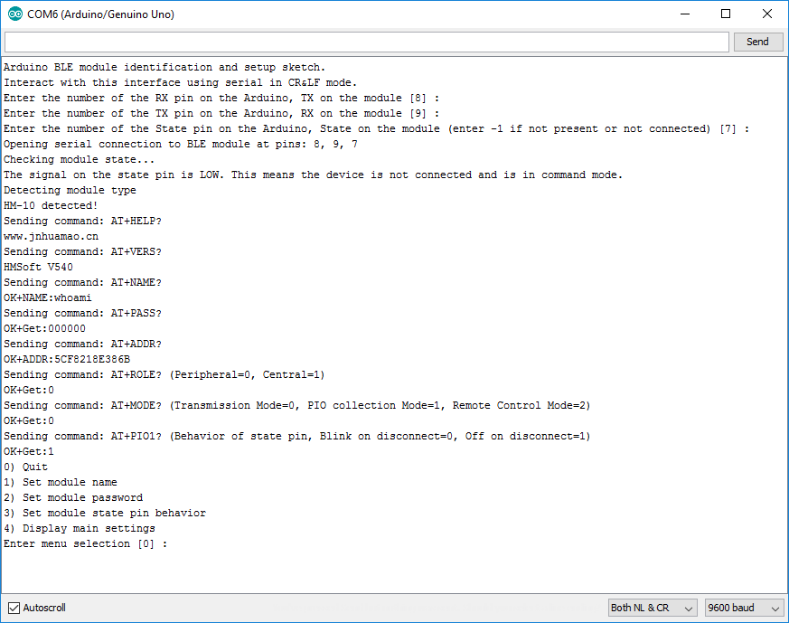
Initializing module and reporting main settings
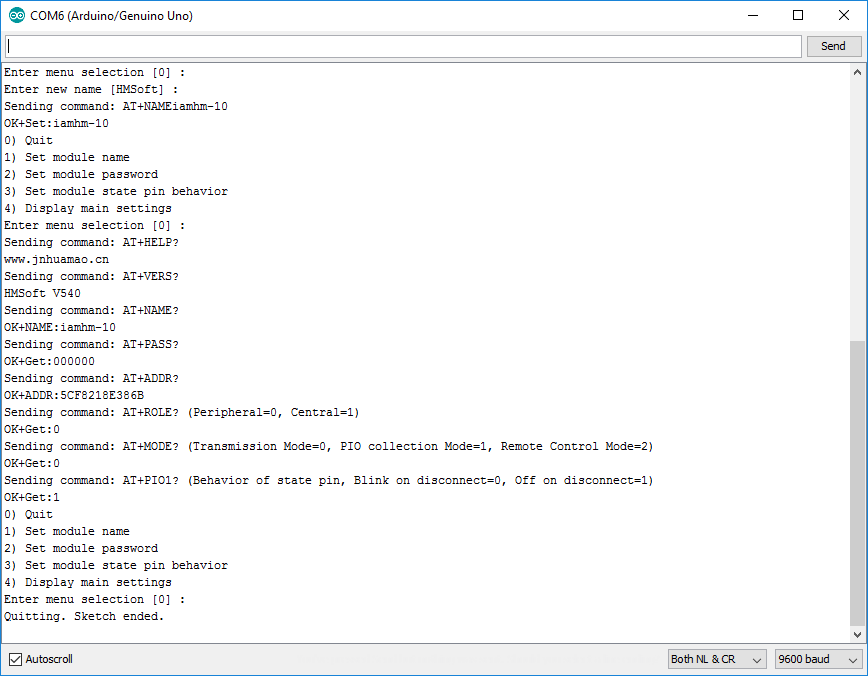
Changing module name using a menu interface
Additional resources
See these articles for more information about BLE and using BLE modules with Arduino
Great article, thanks for sharing!
I just found myself with a CC41 module and immediately found the problems you describe, in particular how different the AT commands are (which don’t even meet Bolutek’s own spec)…
A frustrating experience no doubt.
Hey Rm, happy that you found the article useful. If you have any interesting findings about any special or different commands, please share them. Good luck with your project.
I am facing a problem here. When i tried to pass the AT commands through an Arduino Nano, the CC41 module is not replying back. Can you help me.
Have you written the code for pairing two CC41 modules using arduino? Please help me.
Hi UK, have you tried this sketch https://github.com/ayavilevich/arduino-ble-ident-n-set ? Try it first. If it doesn’t manage to communicate with the module please send links to a schematic of your circuit and a photo of your devices connected together. Can you connect to the module from a smartphone?
With regard to pairing two modules, I have only used such modules as slaves and have no knowledge to share about connecting them together.
Update: Recently I have ordered an HM-10 clone module on ebay that was showing the CC41 model in the pictures. When I got it, I was surprised to find out that it had a different breakout board. It still says ZS-040 on the back, but in thicker text and the (breakout) components on the front are different. A 5 pin regulator is used instead of the 3 pin. The module works ok except that the STATE pin is floating and not functional. The module has a slightly different AT-command names and identifies itself as MLT-BT05-V4.0 and MLT-BT05. Please we warned about the STATE pin and please post your experiences if differ. Identification support was added to the “arduino-ble-ident’n’set” sketch. Read more here: http://blog.yavilevich.com/2017/03/mlt-bt05-ble-module-a-clone-of-a-clone/
Pingback: MLT-BT05 BLE module – a clone of a clone?? | Arik Yavilevich's blog
Pingback: Fixing a bad STATE pin on an MLT-BT05 BLE module | Arik Yavilevich's blog
I bought a Arduino-Android-IOS-HM-10-BLE-Bluetooth-4-0-CC2540-CC2541-Serial-Wireless-Module. i connect with my arduino uno. my android phone paired. i try to connect my blutooth app not work. AT command also not work. please help to me ebay link – http://www.ebay.com/itm/311567433651?_trksid=p2057872.m2749.l2649&ssPageName=STRK%3AMEBIDX%3AIT
Hi GM, first did you get a module that is like in the photo of the listing or different? It happened to me that I got a clone that was different from the clone shown in the eBay listing. Please post a photo of your module. Second, did you perform logic conversion from 5V to 3.3V using a conversion module or resistors? Please post your schematic.
HI. this is my my hm-10 module pictures. please check. I tried it. i got some message please check it also.
https://www.dropbox.com/s/pq3imt0do4nh944/WhatsApp%20Image%202017-04-22%20at%2011.28.38%20AM.jpeg?dl=0
https://www.dropbox.com/s/ce867jqvrxvv8ml/WhatsApp%20Image%202017-04-22%20at%2011.28.39%20AM.jpeg?dl=0
https://www.dropbox.com/s/05d2xzg3ic0clb5/WhatsApp%20Image%202017-04-22%20at%2011.28.40%20AM.jpeg?dl=0
https://www.dropbox.com/s/z8o2gl1cmc14r93/WhatsApp%20Image%202017-04-22%20at%2011.28.42%20AM.jpeg?dl=0
my hm-10 module damage or need to make any setting?
Hi GM, your module is using 3.3V for the logic lines but your arduino uses 5V. You need to have conversion. See this link for more details: https://electronics.stackexchange.com/questions/280500/why-do-you-have-to-use-a-voltage-divider-with-hc-05-bluetooth-module-arduino
Hello,
I have read the publications you did on the HM-10 and have clarified several doubts I had. Thank you very much for the time you have spent on this and the willingness to make it public.
According to your publication, everything seems to indicate I have a CC41-A in my hands.
I managed to establish the communication between two CC41-A modules, each one connected to an MSP430 (TI), but if I have three modules working, I do not know how to get only the two I want communicated.
Also, after the communication is established, how do I stop it by using commands o other software way?
Regards
Ag
Hi Ag,
Glad you found the articles useful.
Using these modules as masters is pretty challenging. There are many limits. For example you can only have one connection at any time. There are other modules, with a lower level of control, that allow for several connections. You didn’t specify what “topology” you have with three modules, but I assume one is master and the other two are slaves. It is then up to the master to disconnect from one and connect to another. To make things difficult, once you are in data mode you can’t send AT commands so you have disconnect.
I have not used these modules as masters, so let me throw some ideas at you and hopefully you can make this work and post an update for others to learn from.
1. Get a module with a BRK (break) pin, this should allow you to disconnect (break) the current connection.
2. Power cycle the module, I guess you would use a transistor.
3. Use 4 modules, where each slave will have its own master.
4. Solder connection to the daughter board’s pin 23. It should be the disconnect pin. http://img.banggood.com/file/products/20150104013145BLE-CC41-A%20Spefication.pdf
5. Get manual control over master/slave state through pins 27, 28. Perhaps changing master to a slave state will allow you to reconfigure it. http://wiki.yfrobot.com/ble4.0/BLE-CC41-A%E8%93%9D%E7%89%99%E6%A8%A1%E5%9D%97%E6%8A%80%E6%9C%AF%E6%89%8B%E5%86%8Cv2.1.pdf
Good luck.
hi,
i tried to change pin via
AT+PIN4529but it respond backERRcould you help me ? Thanks
Hi, I think it has to be 6 digits. Try
AT+PIN452911.Thanks for the brilliant article.
I’m making a board that’s essentially a teensy 3.2 reference board with a host of other components; i have a very small area for a feature i want to add that is on-board BLE.
I know there are some decent nordic ICs about but i only have about 2cm^2 of free space.
My question is, do you think it’ll be semi-trivial to take the reference CC2541 design with parts of the breakout board, and add it to my custom board, or will i need to upload difficult-to-find firmware to the CC2541?
I’m open to any suggestions,
Thanks again!
Hi Ben,
A Teensy 3.2 board should be 3.3V, so you don’t really need the logic that is usually found on the breakout board.
Designing good RF circuits is difficult. There are grounding issues, etc. You should avoid designing your own unless you are into RF.
I suggest you take an HM-10 or HM-11 (even smaller, less gpio) module without the breakout board and solder it to a place on your board. See the documentation about the recommended placement so the antenna is in an optimal location. Sometimes it has to be “in the air” and sometime on a certain edge.
These “open stamp” form factor modules are designed for this purpose exactly. Search Google images for HM-11 and you will see examples.
With regards to firmware, I have not tried it but, there are articles showing how to flash new firmware to the CC2541 chip, including flashing original HM-10 firmware to the CC41. For example, see https://forum.arduino.cc/index.php?topic=393655.0 . Doesn’t look too difficult.
Good luck with your project.
Thank you for getting back to me. I have indeed been eyeing up the HM-11 but it’s just a tad too big. I may go for it though by making the board bigger, will be be trivial to pull out break/state/enable pins to the teensy from the HM-11?
Also, do you have any opinions on the Simblee RFD77101 and/or the laird BL652 series modules? The latter especially isn’t THAT much more than the HM boards, but i bet they’re in a different league, maybe overkill for my project.
Thanks.
Hi Ben,
As far as I can see, the HM-11 is 18*13.5*2.2mm which is under 2cm^2.
The function of the pins will depend on the firmware. The pin layout can be seen in the spec: http://fab.cba.mit.edu/classes/863.15/doc/tutorials/programming/bluetooth/bluetooth40_en.pdf
I have no experience with the other modules you have mentioned. They do seem to be more serious. They have FCC and CE certifications which might be desirable for your project.
Hi Arik,
After some thought i decided to put the BL652 on hold, opting for the HM-11; i don’t know how i’ll fit this (and a micro vibrating motor) on the remainder of this board, but when there’s a will there’s a way.
I’ll aim to get the antenna handing off the top side.
I have been looking through documentation and pinouts, but i was hoping you could point me in the right direction with going about setting up inputs to the hm-11 for break/state/enable. I can see the pinout in the document you linked, but it’s not clear which pins correlate to what, is this all determined by firmware?
Hi Ben,
Challenges are fun, right? 😉
Most of the pins are GPIO, so they depend on the firmware. Could vary between the different clones. Usually PIO0 is “key” which can function as “break”, PIO1 is “LED” which can represent “state” and be visual indicator and PIO2 is pure logical “state”. I believe “enable” is a feature of the breakout board, and just cuts the power to the module. I have never used it.
Thanks, i’m just matching up the pinouts from a schematic in your article about the clone of a clone here to the schematic in the document you provided on page 10. Sadly the pin numbers do differ a tad but i think it should all be ok, i might just go crazy and pull all the GPIOs of the HM-11 to GPIOs of the uC as a safety, maybe with solder jumpers in front of each.
I thought about using enable to totally kill the BT module to save power, as this is a battery powered project (teensy’s not the best choice but i had written the complex firmware last year, don’t want to look at it again let alone port it to some other architecture :p )
One question i had about the schematic i linked above from your other article; at P0_6 there is a switch to toggle the HM-11 between master and slave. I’ll attach this to a GPIO to be safe but if i just had say two HM-11 modules (or two HM-10’s), and i wanted to send and receive data between the two, would i need to change between master or slave? Or should i just set slave for both?
Thank you for all of your advice and help so far!
I’ve got something like this, hopefully it works :p
Hi Ben,
Actually, connecting all the pins to the uC can be a good idea. I suggest you also make sure you have access to the pins needed to program the CC2541. This way you can later write a different firmware but still use all the pins.
If you want to kill all the power you will probably need to add a FET of some sort. Or you can keep the BLE module in sleep state and wake it with AT commands or GPIO signal.
With regard to slave/master mode. Even though some modules allow this to be set through a pin, this state can be set by an AT command, so the usefulness of the pin is limited.
If you want to have communication between two BLE devices one would have to be a master. Perhaps you should get two modules in their breakout form and play with them a bit before you commit to this design. BLE is good for communicating to a phone or some base station device, but is not the best option, for example, for mesh network. So the right choice will depend on your intended use.
Hi Arik,
Thank you so much for your help and advice. I’ve taken all of it on board as i now have all the pins pulled out. I don’t think the HM-11 can be set master/slave by a pin anyway so i will rely on the AT command (i’m assuming they’ll be similar, i’ll definitely use your ID code and let you know).
Also you make a good point, my space now is ridiculously limited so i’ll rely on the sleep commands instead of a FET to turn the module off.
I’ve somehow managed to fit everything onto the board!
My intended use for BT in this project is simple: I have teensy that processes sensor data. i have 1 FSLP sensor breaken out wirelessly sending filtered data. i want bluetooth to be the protocol. So I assume i need to set the teensy side BT as master and the breakout side as slave, (breakout will probably just use a cloned HM-10). I don’t think this is particularly complex, would you say i’ve chosen the wrong architecture/setup for this intended purpose?
The board will look something like this, i think the very bottom of the ant is covered by the mother board but the majority of the ant is ‘in the air’.
board
Hi Ben,
Nice PCB design work.
If I follow you correctly, you are going to have 2 FSLP sensors on the board directly and an additional one which is wireless. The wireless one will be connected to another uC and an HM-11/10 in slave role. The main board, which is BLE master, will then pull data from the wireless unit. Sounds doable. I have not tried something like this myself yet, but I don’t see a reason why it shouldn’t work.
Thanks for sharing, let us know how it works.
Thanks.
Yes you got the design down perfect. I’ll let you know how it goes.
Do you know how one can go about setting up a bluetooth HID, so i could ‘create’ a hid device (say keyboard or bluetooth) and have it show up as a hid device on a phone (via bluetooth)? I’m not sure what this requires.
Hi Ben,
Yes, BT HID is based on the “older” BT, not BLE. So you can do with something simpler.
A cheap way to do this is to hack an HC-05. See https://www.youtube.com/watch?v=BBqsVKMYz1I
But there are dedicated modules for this, such as:
BlueSMiRF HID – https://www.sparkfun.com/products/retired/10938
Bluefruit EZ-Key HID – https://www.adafruit.com/product/1535
It seems it is also possible to reprogram the CC2541 : https://github.com/rampadc/cc254x-hidKbdM but not sure if there is a good firmware available. Didn’t try it.
Hi Arik,
That was very interesting. I researched the two dedicated HID devices and found they’re a bit clunky on android, likely due to their age and stack architecture. There must be newer alternatives, but that HC05 mod looks very nice. I have one of those modules, i’ll see if i can use an ftdi to write the RL52 firmware onto it.
Thanks a lot for the links!
I have spoken to a guy at sparkfun, he suggested i can use a bluetooth module as a simple uart passthrough if i already have usb HID output, and have bluetooth HID that way. (I do already have usb hid setup as i have a teensy setup as a mouse). If that’s possible then that’d be brilliant, does this make sense to you ?
Hi Ben,
Yeah, that makes sense and should work but it won’t show on your phone as Bluetooth HID. It will be a USB HID and you will have to plug it in the USB OTG port of the phone. Right?
So it’s more like a DIY USB wireless keyboard/mouse. With BT for the wireless part (internally).
so the idea was to remove all that double hm11 stuff, and just have 1 board with 1 bt module (atm not decided but i have a board being fabbed with a hm11 footprint), and have an existing setup where usb hid data is talking to a phone via otg, have that wire removed, by ‘passing through’ the usb hid data to the bt module.
Makes sense?
Hey Ben,
No. 🙁 I don’t follow you on this one.
Got an account at hackaday? My account page is at https://hackaday.io/ayavilevich . Happy to take this topic to the chat, it is no longer on topic for this post.
Pingback: Fochica™ – Forgotten Child in Car Alert | Arik Yavilevich's blog
Hi arik,
Great post, it helped me clear many doubts about the genuineness of hm 10 i have. But i am having problems in converting hm10 into a master/central device which can scan beacons and their uuid, major and minor.
Hi Mohak,
Thanks. I have doubts that HM-10 will be a useful device for scanning beacons. It is not well suited for that. It can barely function as a beacon itself. I suggest to use something else. Perhaps an ESP32.
Pingback: Fixing a bad STATE pin on an MLT-BT05 BLE module | Arik Yavilevich's blog
hi can i test it on esp8266 ?
Test what exactly?
Connect the ESP to the module. Mind proper voltage levels for power and logic. Then use AT commands as you would do with an Arduino Uno, etc.
Hi Arik, I found out your article very helpful!!
After reading it I solved some problems that were holding me back 🙂
I have 1 question thou.
The thing is, when I install a beacon scanner app on my android phone and click my iBeacon device on that app, they are connected(paired maybe?) so AT command does not work on my PC anymore. I found out that there are ‘ AT+ADTY3’ and ‘ AT+DELO2’ commands, which disables the pairing, but it does not work (no answer) cuz mine is cc41-a. I found out that those commands are only for HM-10s, not CC41-a.
So, my question is, is there any command that disables the connection to my cc41-a? Or do I have to ‘flash the HM-10 firmware onto my CC41-A’, which some guys on the internet recommends?
Sorry for the long comment and thank you again for your kind and great article!
Hey FakeHM-10Owner ;),
As far as I know the clones are not good as beacons. Software-wise, they are programmed for functioning as serial devices. They have different firmware than the original. Hardware-wise, they lack a “slow” oscillator which can cause them to be less power efficient than the original HM-10 in beacon scenarios. This is because their sleep between advertisements could be less efficient.
I recommend that you try to flash your board to a latest official HM-10 firmware and see what happens. If you are power sensitive, definitely compare beacon power consumption with a genuine HM-10.
Thanks for your reply Arik!
I’m gonna go flash my board and report the result here 🙂
www. jnhuamao. cn tried to infect my pc with malware, Beware there.
Thanks for the Info, was much help!
I can confirm that some downloads there are identified as trojans. See my warning about their site in the post.
Arik,
Do you have any examples of arduino code where we can get it to send some signals to an IOS app. My CC-41 module is responding to your basic sketch and am able to get the desired information. And also my CC-41 is not getting shown in the devices under bluetooth devices but am able to see it as BT05 in the Serial IOS app (HM-10 Bluetoothe serial lite)…
Hi Lawrence,
It functions as a serial device. When connected, anything you send to it will be sent to the other side.
I don’t have a “simple example”, for that you may want to Google around.
For a more advanced example, see https://github.com/ayavilevich/arduino-ble-ident-n-set/blob/master/arduino-ble-ident-n-set.ino for communicating to the module over a serial connection.
Arik,
Thanks for responding….. but under my bluetooth devices in IOS.. it does not get listed also for me to connect.. am I missing something ?
Hi Lawrence,
Not familiar with iOS, but on Android BLE devices don’t have to show up in the list for them to work. That list is primary for non-BLE BT devices. You should use a special purpose BLE scanner app for iOS.
Thanks Arik.. I will see if I can find more
Thanks for the code. You might mention that you need to set the speed of the Serial Monitor to 115200… 🙂 I thought it was not working, and then I thought … hmmm, what is all that gibberish? It worked just fine at 115200…
For some reason, when the program sent the command AT+TYPE?, it did not get a response. All other commands worked, and it identified it as an HM-10 (which it is). When I connect directly (via the usual dual serial method) the command works fine. Dunno why.
A question for you: I am wanting to use this module in master mode to allow me to have the Arduino receive ascii characters from a bluetooth keyboard. However, I have been unable to get any bluetooth keyboard to work with the module. I thought there was a ‘scan’ function AT+DISC? but I get no response from that command. Any thoughts on how to create a connection with a keyboard would be wonderful…
Hi Eric, thanks for your feedback.
A common misunderstanding is that Bluetooth or BLE are all the same. In fact, there are many sub types and protocols. A serial BLE module, like the HM-10, is not programmed to talk to Bluetooth HID (Human Interface Device). The HM-10 will only talk to other similar serial BLE devices or computers/smartphones in serial BLE mode.
To communicate with a BT keyboard first identify if that is a BLE or regular BT keyboard, then look for appropriate modules to support the specific use case. For some cases and with some effort, you could reprogram the HM-10 module to run the BLE HID protocol.
For more information research the following keywords: cc254x-hidKbdM, ESP32, BlueSMiRF HID, Bluefruit EZ-Key HID, RN-42, etc.
Thanks, Arik! I will use your search terms and see what I find!
Pingback: Should you throw away your CC41 HM-10 clones now that Android 8 is here? | Arik Yavilevich's blog
Thank you for your effort.
I want to ask you question..
now .. i have cc41 connected with ttl-uart with terminal and bluetooth terminal at mobile app
all is ok
but i want to make the slave (cc41 module) to disconnect the connection with the mobile by software command , Can this happen ?
or only work in hardware pins in module ?
Hi ibrahim,
There is no way that I am aware of to disconnect the connection from the side of the salve except for resting the power to the CC41. This is because once in “connection mode” you cannot send “at commands” any more.
Hello Arik,
firstly thank you very much for your effort you have put into this site! Its really wealth of information and I appreciate very much.
I recently bought a BLE CC41-A module (by accident) and implemented kind of a small arduino chat programm that lets you communicate with your phone over serial monitor:
https://bitbucket.org/kaulquappe/arduinonanobluetoothchat/src/master/
I have seen that there is a app called bluino that makes it possible to program the arduino over bluetooth:
https://www.instructables.com/id/Program-Your-Arduino-With-an-Android-Device-Over-B/
I wonder how this is done?
I thought of entering command mode from the mobile phone and issue an AT command that toggles a pin on the bluetooth breakout port.
Maybe this could work with the AT+BEFC or AT+AFTC (Query/Set Module pin output state) command?
This again would reset the arduino so that the bootloader can flash the chip with the code written over the serial bluetooth device (https://playground.arduino.cc/Main/ArduinoReset).
As far as I know one has to be connected to the bluetooth device in order to communicate. But when you are connected you are in data mode and cannot issue AT commands, is that right?
So I wonder:
* how to enable/switch to command mode (and back) from your mobile phone ?
* how can I issue a command that toggles a pin on the bluetooth breakout port so that I can reset the arduino?
* how can I send the program code shortly after the arduino has been resetted in order to flash it ?
I guess that it somehow must work because the Bluino app does it too. But I am not sure how :P.
regards,
Paul
Hi Paul,
The Bluino instructable shows that the STATE pin on the BT module is connected via a capacitor to the RESET pin of the Arduino.
So when the phone connects to the module, the Arduino resets.
I believe the cap is there to give some delay to make things in “sync”.
If you are going to reproduce this, mind that they are not using a BLE module, they are using a (classic) BT module, a HC-05.
There is no easy way to control mode remotely (or even locally) with the majority of the BLE modules.
Only the original HM-10 offers commands to control general GPIO but those are somewhat complex.
Hi Arik,
ak, i understand. So he can flash the arduino, but not use it for normal communication anymore, i guess.
Do you know if there is a way to enter command mode over the mobile phone ?
Hi Paul,
Unfortunately I don’t know of such a way.
The only way that I know (with the above described firmware) is to disconnect.
Thank you for your kind help!
I just ordered 2 original HuaMao boards here:
https://www.aliexpress.com/item/HM-10-from-HuaMao-Bluetooth-4-0-Module-Transparent-Serial-Port-BASE-PLATE-NOT-INCLUDED-HM/32837893282.html
Maybe i can get it to work – who knows 😉
Hi Paul,
Worth a try. Let us know if you manage to do anything interesting.
In the worst case, you can use another Arduino to manage the connection and programming of the first Arduino.
Yes – I will let you know if I find out something interesting.
I had a closer look yesterday and it really seems to be impossible to switch between command and data mode via a bluetooth connection. It seems that in order to toggle pins via the AT+BEFC or AT+AFTC command, you first have to set the remote bluetooth device in AT-Command mode via a direct serial line (see: http://www.martyncurrey.com/hm-10-bluetooth-4ble-modules/#HM-10_stand-alone_MODE_2_and_controlling_LEDs).
Now I am also thinking of issuing a command over bluetooth to the arduino mc that lets it reboot in bootloader mode via software. It then probably could be flashed via the bluetooth connection on the hardware serial port.
Thanks for this article Arik, I had lost my interest in the JDY-09-V4.3 I bought weeks ago but now I can finally use it.
Keep going with this blog!
For the two products profiles here, are there any schematics of the carrier board ?
Are there parts list of these boards ?
Typically you would have a very basic schematic in the datasheet document of the module. For example: http://blog.yavilevich.com/wp-content/uploads/2017/03/MLT-BL05-diagram.png
Not more than that.
That is the schematic for the HM-10 module.
I am looking for the schematic for the carrier board.
The schematic of the voltage regulator and level shifters.
That is a schematic for the carrier board with the module as just a “black-box” component. You can see the led and the resistor in the schematic which are on the carrier board. You are right that it doesn’t show the regulator, but that one is easy to imagine.
Most HM-10 boards come with no logic level shifting, so you should not expect to find a schematic like that easily.
I am trying to connect an HM-10 to an Sparkfun FTDI Basic module.
As I incorrectly thought that the parts on the carrier board had a level converter, I connected the HM-10 to a 5V FTDI Basic adapter.
It did not work.
I looked at all and many docs I could find, any nowhere could I find a statement stating that the Rx/Tx lines were 3.3V.
So now I might have two modules that are toast.
That’s the problem with “Black Boxes”, you will never know what you may get till it’s too late.
Is there a reason that the carrier boards are a secret ?
Most HM-10 modules that I have seen have a “LEVEL: 3.3V” text on the back.
http://blog.yavilevich.com/wp-content/uploads/2016/12/CC41-back.jpg
What does your say?
Anyway, they normally don’t break on first use with 5V. Some people use them with 5V regularly. Just connect properly and try again.
The reason why there are no published designs for the boards is because this is the way the Chinese manufacturers are protecting their IP one from another.
Aril- Thank you for efforts, this was a very informative article.
Do you know of a supplier which sells KNOWN GOOD – Genuine JNHUAMAO HM-10 boards? Additionally, do you know of a supplier of 6-pin “daughter” cards with GENUINE HM-10 boards attached?
Just this one: https://www.ebay.com/itm/HM-10-BLE-Bluetooth-4-0-CC2540-CC2541-Serial-Wireless-Module-Arduino-Android-IOS/311550871992
ARIK,
Thanks for your reply. I was very hopeful, and ordered some via your link. The image that the seller post IS of an actual HM-10. But, unfortunately THEY ARE NOW SHIPPING COUNTERFIT ITEMS not genuine HM-!0.
Fortunately I was able to find genuine HM-10s at DSD TECH’s AMAZON store.
Thanks again for your efforts.
Hey, np. Thanks for the information. Hope you got a refund.
I am having trouble identifying my exact module
Setup:
-Arduino Mega 2560 board
-Bluetooth Module (that appears to be trash so far)
By connecting them like this:
RXD to RX0
TXD to TX0
RXD, TXD on bluetooth
RX0, TX0 on board
I managed to comunicate using arduino ide’s serial monitor with the bluetooth module:
https://i.imgur.com/uf7uAgB.png
Commands work like this [command][parameter] (case insensitive for commands):
AT+PIN000000 where pin and password need to be 6 digits
AT+NAMENewName
But i cannot indentify which model this is.
The arduino-ble-ident-n-set is unable to identify it (but i’m unsure if i put the correct pins when it asked me for them; i tried with 0 1 -1 and 1 0 -1 as well as 14 15 -1 and 15 14 -1)
I’m asking because i am unable to pair it with any phone that i have Android versions:
-4.4.4: I can write the pin code but it acts as nothing happened and doesn’t pair.
-6.0.1: Unable to comunicate with device.
-8.1.0: Unable to pair with BT05 due to wrong pin; a box to insert the pin shows up for about 0.7 seconds then closes
Hi,
RX0/TX0 is a hardware serial port on the Mega that is used for the Mega to communicate through the USB. You probably don’t want to use it for communicating with the BLE module.
Either use two “simple” digital pins and SoftwareSerial or choose another available HardwareSerial on the Mega and change arduino-ble-ident-n-set to use it. You can configure arduino-ble-ident-n-set to use a HardwareSerial device if you define a SPECIAL_SERIAL value. See source code but mind this might be an advanced configuration for a beginner.
Thank you for that clarification.
arduino-ble-ident-n-set now identifies it as CC41.
Now the problem is to make it pair with the phone.
I plan to make my own custom APK.
Before i attempt flashing it with HM-10’s firmware, would you suggest any other method of testing/pairing/etc to see if CC41 works as it is?
All i need it to do is just send me information from sensors to my phone.
Install “nRF Connect” app. Use it to communicate with the module. These BLE modules don’t require pairing with default settings.
This module will most likely not work with Android 8. See https://blog.yavilevich.com/2018/04/should-you-throw-away-your-cc41-hm-10-clones-now-that-android-8-is-here/
Alright after installing nRF Connect i managed to find out the clone that i have is not affected by Android 8 bug and it works without having to burn HM-10’s firmware on it.
Now all i have to do is make an app.
Do you have any information about how to go around doing this?
I can’t seem to find examples for SDK 19 (Android Jellybean)
Hey,
So this is an CC41 that works fine with Android 8? Can you share more details such as output of arduino-ble-ident-n-set, name, version, module photos, etc?
You can find a BLE sample at:
https://github.com/googlesamples/android-BluetoothLeGatt
In my very first comment ( https://blog.yavilevich.com/2016/12/hm-10-or-cc41-a-module-automatic-arduino-ble-module-identification/#comment-20553 ) you’ll find a imgur link with AT+HELP, name and version; arduino-ble-ident-n-set’s only additional output is that it says it’s a CC41.
The module looks identical to this AT-09: http://www.martyncurrey.com/bluetooth-modules/#AT-09
The only differences between mine and that one is the version and the default pass/pin being 123456 instead of 000000
Cool. Then it seems this issue was fixed in the V4.4.0 version of the firmware (as opposed to V3.0.6).
If only the manufacturer would release his firmware so old versions could be updated…
Pingback: Flash HM-10 and BT-05 firmware – LouWii's Blog
Brilliant – thanks – after wasting hours trying to switch back to command mode – your test worked (just got to find out what you did now 🙂 ) I DO have a clone! Cheers
Hello, I just want to thank you for all the time you saved me. I was having a problem on 2 HM-10 modules I bought. My mistake was that I changed the baud rates based on the AT commands of the HM-10 and I didn´t knew that the cloned ones had different parameters.
A little more info for you to add if you wish.
I have a BLE module purchased as HC-08. It looks identical to your picture of the CC41 except that it has the little push-button switch at the bottom left corner adjacent to the ‘EN’ pin.
The result of the arduino-ble-ident-n-set sketch:
Arduino BLE module identification and setup sketch.
Interact with this interface using serial in CR&LF mode.
Enter the number of the RX pin on the Arduino, TX on the module [8] :
Enter the number of the TX pin on the Arduino, RX on the module [9] :
Enter the number of the State pin on the Arduino, State on the module (enter -1 if not present or not connected) [7] :
Opening serial connection to BLE module at pins: 8, 9, 5
Checking module state…
The signal on the state pin is LOW. This means the device is not connected and is in command mode.
Detecting module type
CC41 detected!
Sending command: AT+HELP
********************************************************************
* Command Description *
* —————————————————————- *
* AT Check if the command terminal work normally *
* AT+RESET Software reboot *
* AT+VERSION Get firmware, bluetooth, HCI and LMP version *
* AT+HELP List all the commands *
* AT+NAME Get/Set local device name *
* AT+PIN Get/Set pin code for pairing *
* AT+PASS Get/Set pin code for pairing *
* AT+BAUD Get/Set baud rate *
* AT+LADDR Get local bluetooth address *
* AT+ADDR Get local bluetooth address *
* AT+DEFAULT Restore factory default *
* AT+RENEW Restore factory default *
* AT+STATE Get current state *
* AT+PWRM Get/Set power on mode(low power) *
* AT+POWE Get/Set RF transmit power *
* AT+SLEEP Sleep mode *
* AT+ROLE Get/Set current role. *
* AT+PARI Get/Set UART parity bit. *
* AT+STOP Get/Set UART stop bit. *
* AT+START System start working. *
* AT+IMME System wait for command when power on. *
* AT+IBEA Switch iBeacon mode. *
* AT+IBE0 Set iBeacon UUID 0. *
* AT+IBE1 Set iBeacon UUID 1. *
* AT+IBE2 Set iBeacon UUID 2. *
* AT+IBE3 Set iBeacon UUID 3. *
* AT+MARJ Set iBeacon MARJ . *
* AT+MINO Set iBeacon MINO . *
* AT+MEA Set iBeacon MEA . *
* AT+NOTI Notify connection event . *
* AT+UUID Get/Set system SERVER_UUID . *
* AT+CHAR Get/Set system CHAR_UUID . *
* —————————————————————–*
* Note: (M) = The command support slave mode only. *
********************************************************************
Sending command: AT+VERSION
MLT-BT05-V4.1
Sending command: AT+NAME
+NAME=MLT-BT05
Sending command: AT+PASS
+PASS=123456
Sending command: AT+ADDR
+ADDR=88:25:83:F0:F1:BD
Sending command: AT+ROLE
+ROLE=0
Sending command: AT+POWE (0 = -23dbm, 1 = -6dbm, 2 = 0dbm, 3 = 6dbm)
+POWE=2
Sending command: AT+TYPE (0 = No binding, 3 = Do binding (not documented))
+TYPE=0
0) Quit
1) Set module name
2) Set module password
4) Set module power
5) Set module binding type
6) Display main settings
7) Restore default settings
8) Reboot/reset/restart
9) Re-identify module
10) Detect connection state
11) Set role
12) Send custom command
Enter menu selection [0] :
Quitting. Sketch ended.
Hey Brissieboy, thanks for the info. Any bit helps.
Any idea what does the button do?
From what I could find, it appears to enable AT command mode if held pressed on power-up, but I haven’t tested it. Not sure why it would be needed for that function as the HC-08 is in command mode as long as there is no bluetooth connection.
I found some information here:
http://www.martyncurrey.com/arduino-with-hc-05-bluetooth-module-at-mode/
but that relates to the HC-05.
An Ebay item referred to it as a ‘Reset’ button.
Most of the units using the daughter board (ZS-040 & others) have the position for the switch on the daughter board, but it is not fitted.
BTW I have had a lot of trouble trying to communicate from an iphone with this unit. The ‘DSD TECH Bluetooth’ app is the only terminal app that I have found that will successfully talk to it – no idea why at this stage.
Be aware with default baud rate (CC41-A). Mine was 115200 for both I have received.
Hi. I’m building a Bluetooth stereo amplifier. I’ve bought the Arduino 3 x 3 watt amp module, USB 5v booster module , li ion charger module and the hm 10 v4 BLE Bluetooth module. I’ve incorporated a double pole double throw centre off toggle switch to switch between battery or micro USB power. I’ve connected them all up through speakers. I tried pairing the Bluetooth through phone, iPad and laptop. They all fail at finding the Bluetooth. So I downloaded Ble scanner. Now they connect but not bond. I read on line forums that this module doesn’t connect with alot of phones because it’s not the standard classic Bluetooth module and that it’s for low energy applications. When I do power it all up, all I hear in the speakers is a coordinated timed beep distortion sound. So I’m guessing I bought the wrong Bluetooth module for music as it’s a low energy module.
Can I reprogramme the hm10 module through my Arduino uno to be able to used for music like 4.1?
Hi Frank,
I highly doubt you will be able to do audio with the HM-10.
The HM-10 is BLE and audio over BLE is something that was added only recently and it is unlikely that a fairly old module like the HM-10 would be able to do it.
Your best bet is to get a module that is designed for classic BT audio. I am sure there are plenty of options of all-in-one modules with a BT receiver, an amplifier, etc. I don’t have one to recommend.
Hi
My HM-10 Module reads its version as HMSoft V004
Is this old module ? Is there a way upgrade
Hi Eugene,
Probably some fake… I have never seen an HMSoft HM-10 version before that was less than 400.
What is the full output of https://github.com/ayavilevich/arduino-ble-ident-n-set ?
Hi, I have the same problem as Eugene, using your sketch https://github.com/ayavilevich/arduino-ble-ident-n-set it identified as HM-10, however the version is HMSoft v004 and the 32k crystal oscillator appears to be genuine. Some commands don’t work like AT+PASS1234 (AT+PASS? does work but the password never changes), the official upgrading software won’t work and just says “Timeout waiting for response from target”, should I upgrade to v504 using CCLoader?
This is the full output of that sketch:
Sending command: AT+VERS?
HMSoft V004
Sending command: AT+NAME?
OK+Get:HMSoft
Sending command: AT+PASS?
OK+Get:000000
Sending command: AT+ADDR?
OK+ADDR:=A4D578187A3A
Sending command: AT+ROLE? (Peripheral=0, Central=1)
OK+Get:0
Sending command: AT+POWE? (0 = -23dbm, 1 = -6dbm, 2 = 0dbm, 3 = 6dbm)
OK+Get:3
Sending command: AT+TYPE? (0 = Not need PIN Code, 1 = Auth not need PIN, 2 = Auth with PIN, 3 = Auth and bond)
OK+Get:0
Sending command: AT+MODE? (Transmission Mode=0, PIO collection Mode=1, Remote Control Mode=2)
OK+Get:0
Sending command: AT+PIO1? (Behavior of state pin, Blink on disconnect=0, Off on disconnect=1)
Hi, I have the same problem as Leo and Eugene. Is there any solution to upgrade the version? I tried to send AT+SBLUP to enter the upgrade mode, but it didn’t reply any response to that command
Same issue happening that Leo, Eugene and Alfa, any solutions anyone?
BT05 module only works alternate AT commands. No reply on alternate AT commands. How can I resolve this problem? Also no reply after software reboot AT+RESET command.