This article covers a home automation project, in which I extended a control panel of a Rinnai gas water heater with an ESP32. The ESP32 then functions as an interface between the control panel and Home Assistant, a home automation software.
tl;dr, the ESP32 sits as a MitM (proxy) on a few data lines inside the control panel. It parses the protocol and converts it to MQTT messages. It is also able to modify the data on the fly to simulate button presses. The device then shows up in Home Assistant through the magic of MQTT discovery.
Introduction
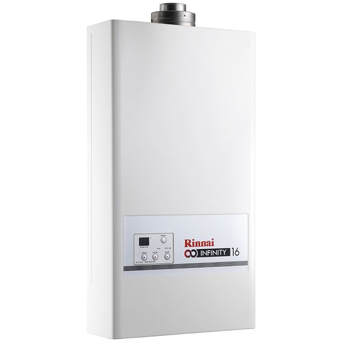
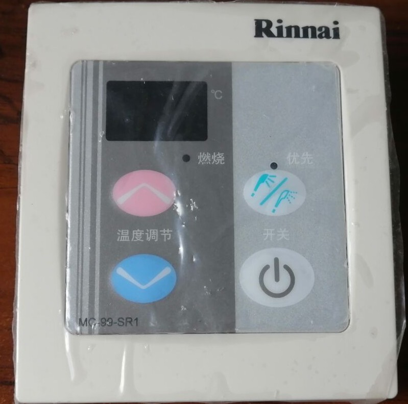
We have a Rinnai Infinity 16i tankless gas water heater at home. It has a built-in control panel where you can turn it on and off and set the desired water temperature. The exact model is “REU-16 FUA-IS”, which is a EU model, but it seems it is similar to other such devices by Rinnai sold in other parts of the world. Overall this is a great product and does a great job at providing hot water to the family on demand.
Our Rinnai is installed in the service balcony and the location is not very convenient. So if somebody wants to turn the unit on or change the temperature it is a hassle. Additionally, it would be preferable to automate the unit and tell it to turn on or off during specific hours of the day, etc. Specifically, I don’t want it to be “on” when there is plenty of hot water available from the solar water heater. At those times it would just trigger for a few moments until the hot water from the solar water tank reaches it, then it would shut off.
Another pain is power outages. Even the smallest outage will cause the unit to reset and come up in an “off” state. Quite annoying to discover that the device is off while you are already in the shower. A smarter controller can help with that.
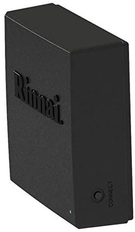
Unfortunately the Rinnai heater is not “connected”, meaning that it is not possible to control it over the network or integrate with it on its own. Rinnai US sells a “Control-R Wi-Fi” module (model “RWM101”) which is an official product that you connect to your heater so you can control it over the network with an app.
The way you connect this Wi-Fi module to the main unit is the same as you would connect an additional control panel (AKA temperature controller). Based on the manual of the heater, it can support up to 3 such temperature controllers. All the control panels are connected in parallel with a two wire “bus” that provides both power and data. The bus is operating at 12V DC with some additional frequencies added to it for data transfer.
I decided it would be fun to integrate with my existing control panel and make it “smart”. It is probably much easier to install the official “Control-R Wi-Fi” module but for me it was not the best fit. First, such modules are not sold where I live and my local Rinnai supplier doesn’t carry them. Second, I wasn’t sure if this will work with my European Rinnai model or if that is something that only works with US units (F vs C, etc). Third, It is not clear how well the proprietary off-the-shelf system integrates with Home Assistant. Forth, the reviews for the official app are not good (2.5 on Google Play, 1.5 on the Apple App Store). Fifth, I was curious to see how this works inside. 😉
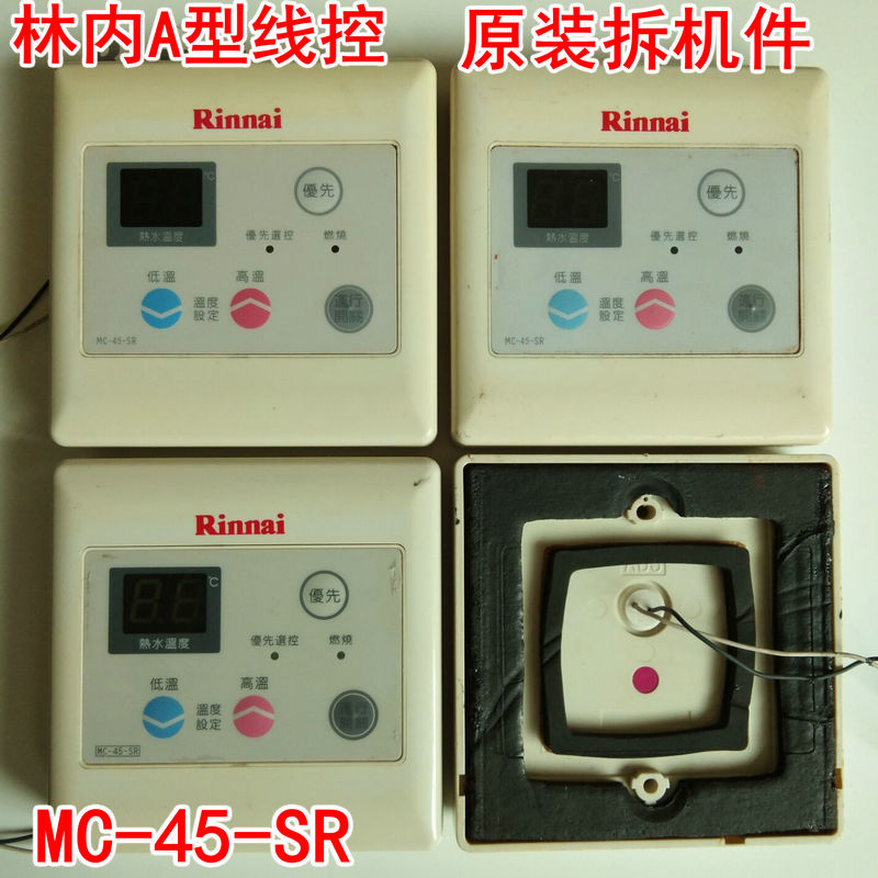
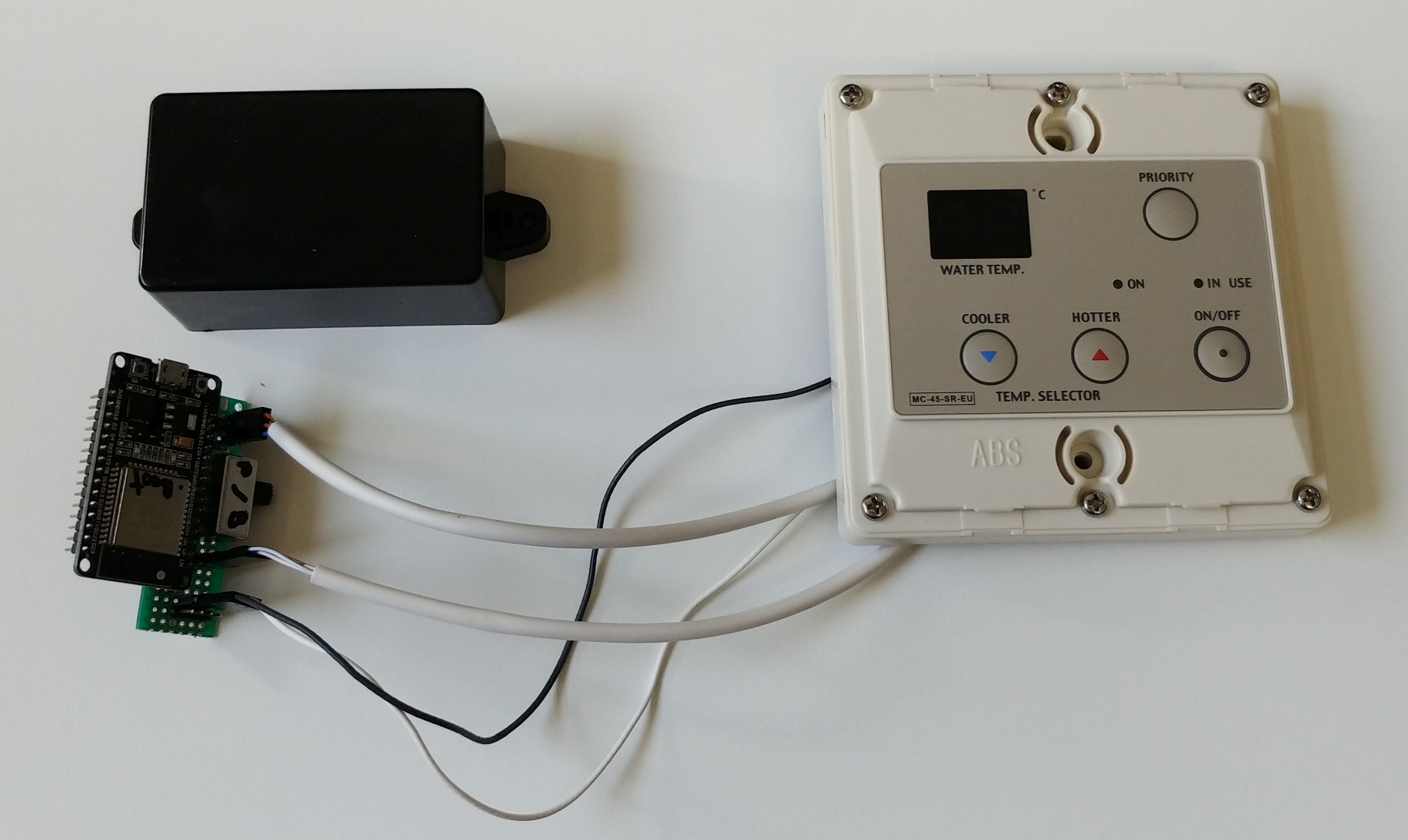
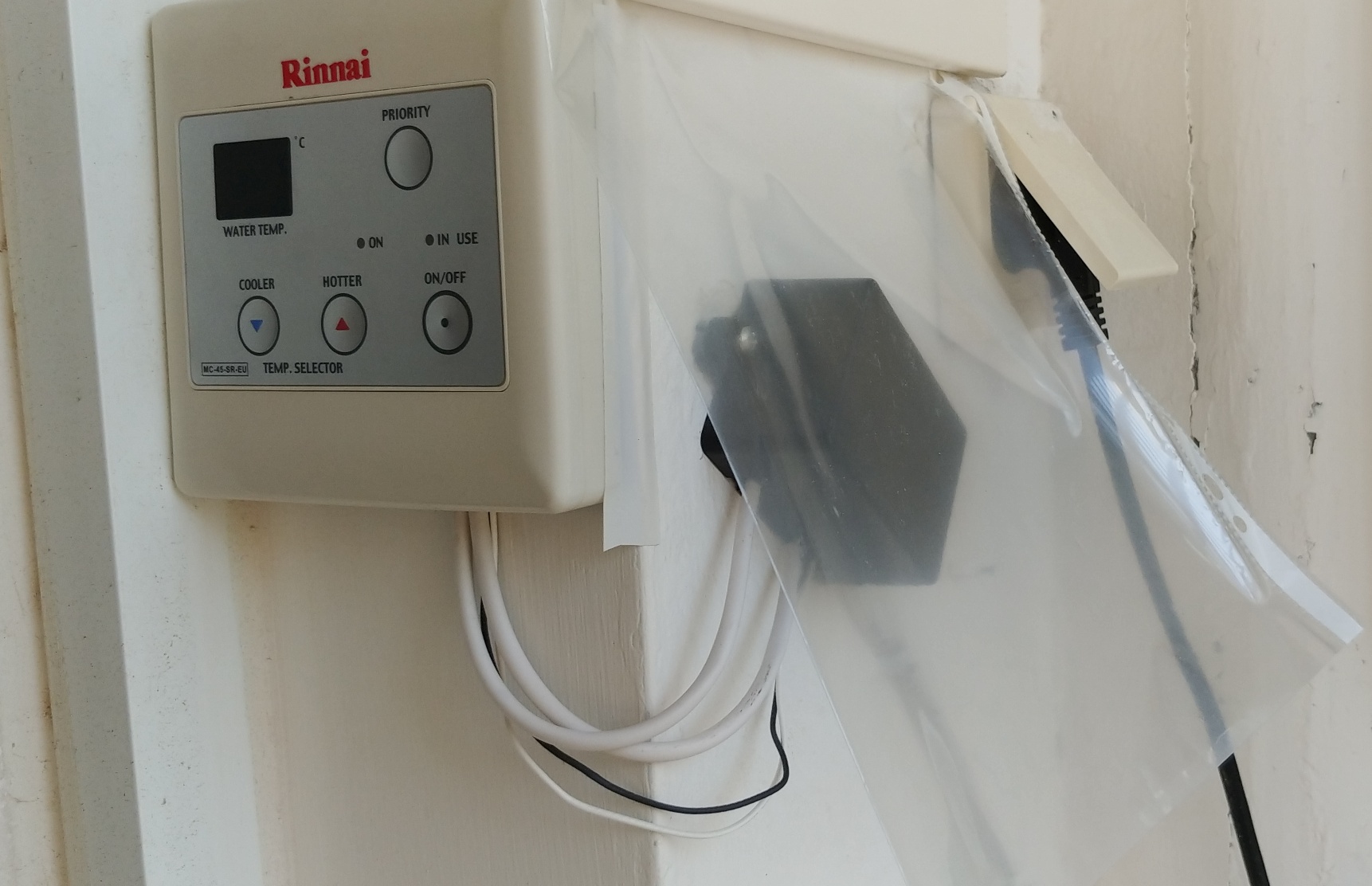
I decided that if I am going to hack into the control panel then I should do it with a spare and that I should disrupt my live unit as little as possible. I went and got a second control panel (model MC-45-SR-EU). This one is the same as the one built-in but with a special mounting adapter it can also be mounted externally. Here you really marvel at the nice Japanese engineering and how they made the control panel concept modular so it works both inside and outside of the main device.

The main heater unit comes ready for integration with an additional panel. There are wires inside to which you can connect some extension cables and then an additional unit. Both control panel units work together at the same time, where only one can control the temperature at a given moment. The control that is “in control” is said to have “priority” and you make a control panel active by pressing the “priority” button on the relevant panel.
Warnings: You might void your warranty during the modification process described below (at least for the panel you will be modifying). Power down the mains connection of the heater when making any changes or when connecting and disconnecting components. Make sure that your “two wire bus” is 12V or some other extra-low voltage. Follow any relevant local regulation.
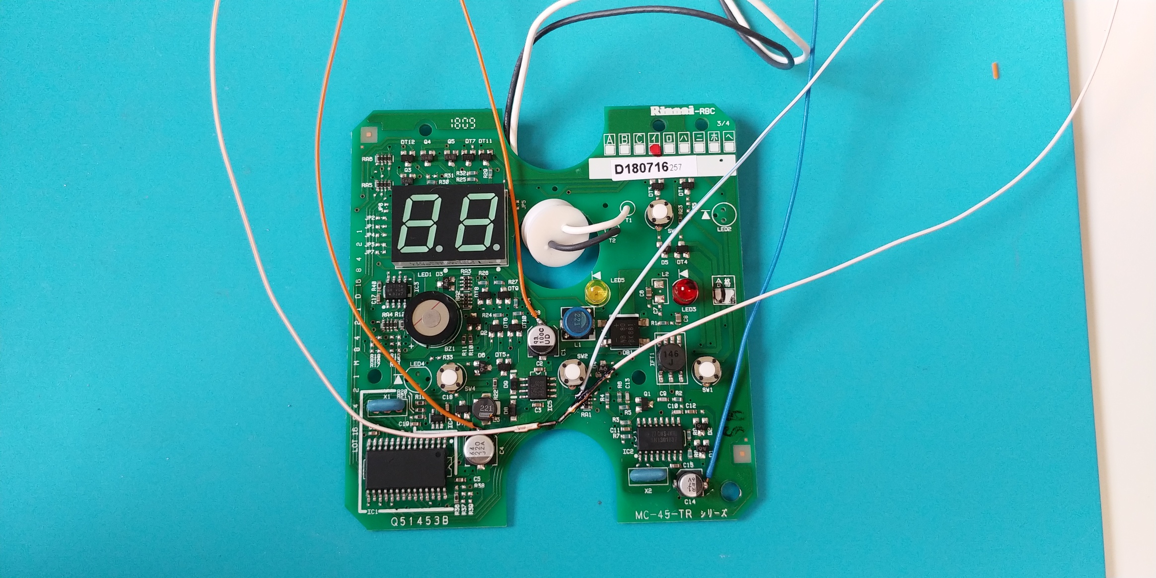
The inside of the control panel
The panel has a PCB inside with various components
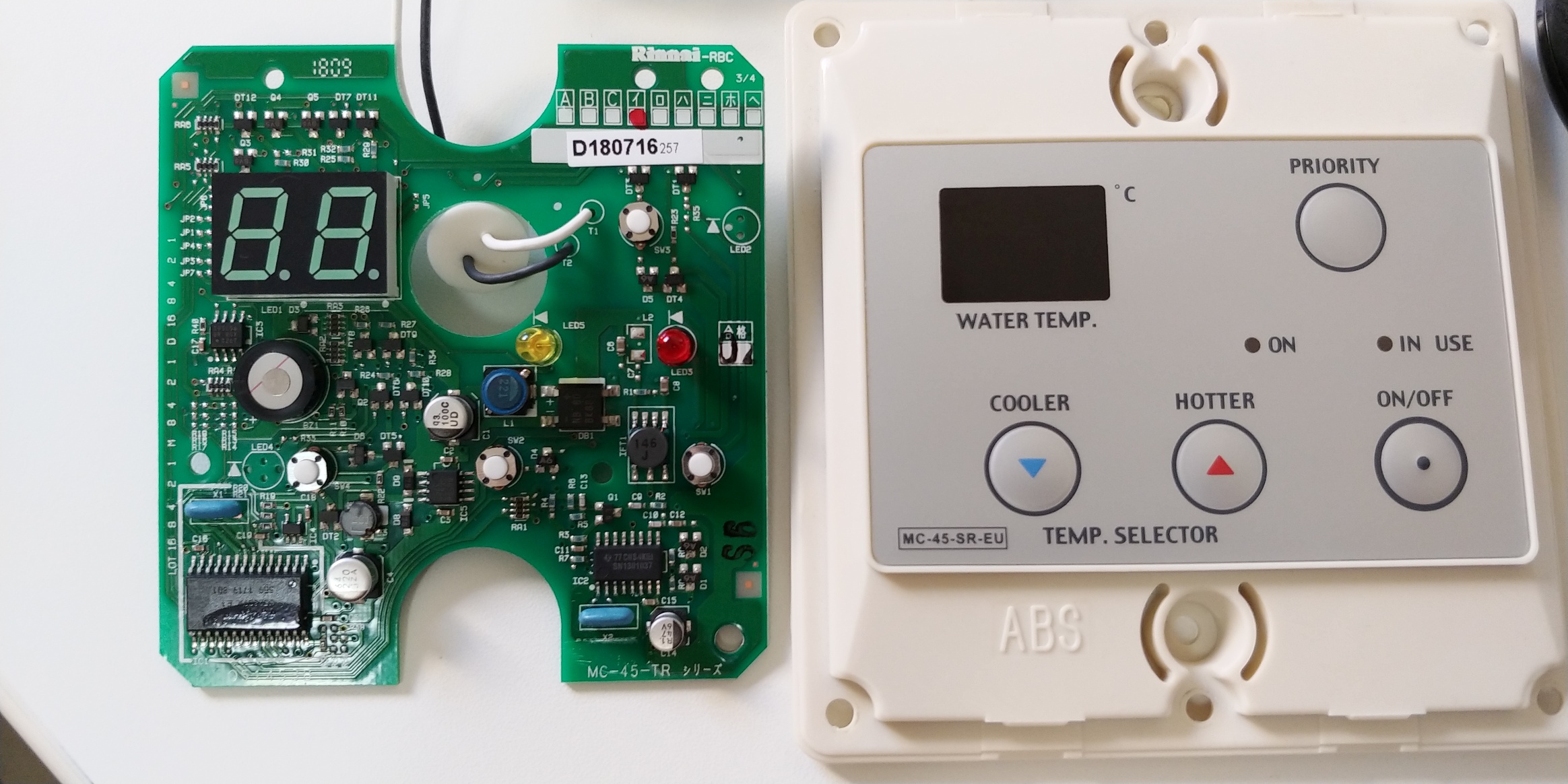
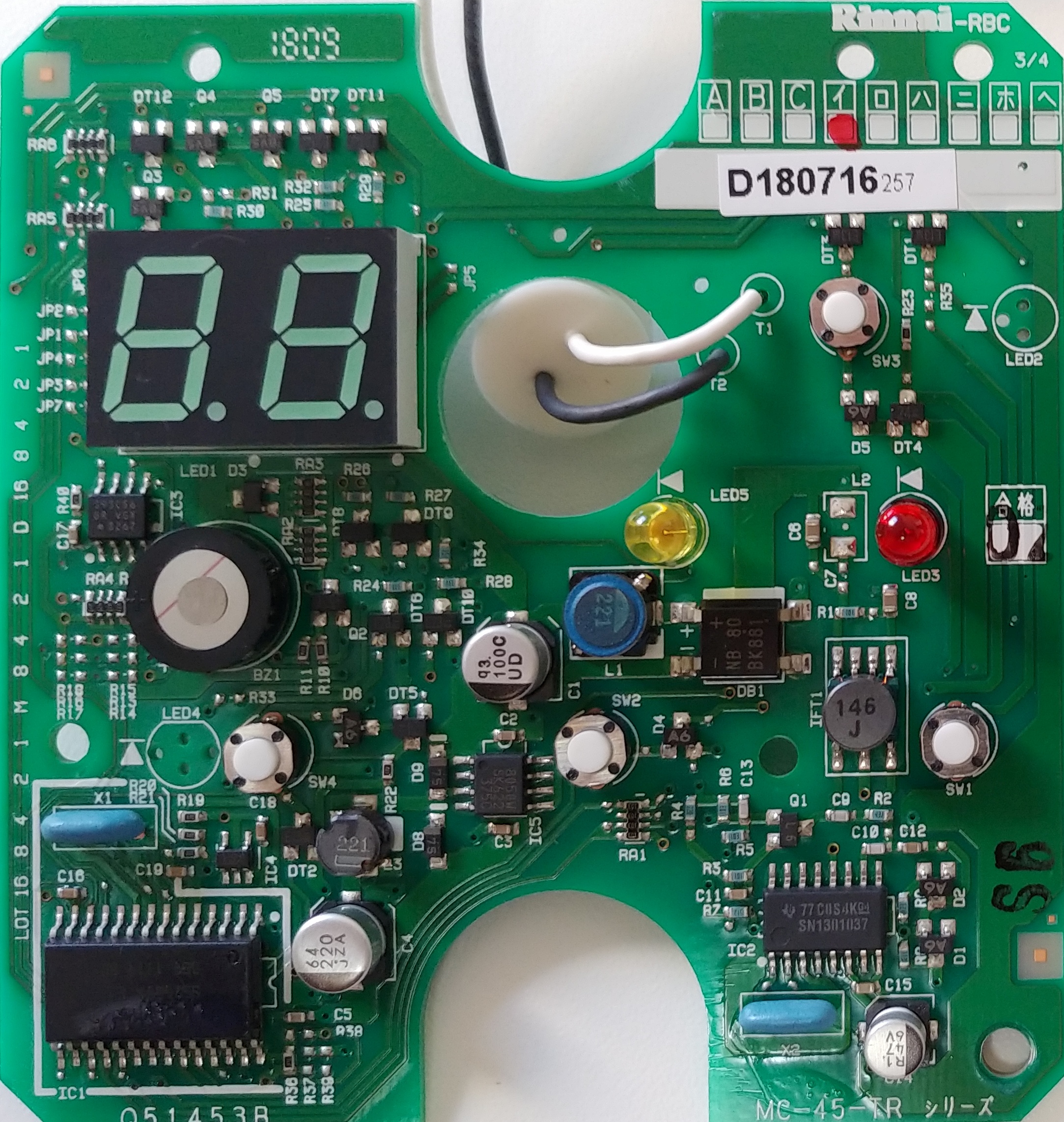
After some tracing and testing, the main components/areas are:
- 2 digit LED display (LED1) [LTD-5250G-NBJ]
- Various LEDs (LED3, LED5)
- Various switches (SW1, SW2, SW3, SW4)
- Analog circuitry for power line communications (IFT1, D1, D2, Q1, etc)
- LED related transistors (Q3, Q4, Q5, DT6 – DT12)
- Switch related transistors (DT1 – DT5)
- An unknown MCU (IC1) [EQ-610V3]
- A custom TI power line communication (PLC) chip (IC2) [SN1301037 SN1301037PWR?]
- A 12V rated buzzer and circuitry (BZ1, Q2)
- An EEPROM (IC3) [S93C56]
- Unknown IC (IC4) [EC 80 76]
- Buck regulator IC (IC5) [SI-8050W-TL]
- Diode bridge rectifier (DB1)
After analyzing the circuit, getting a high level understanding of it and doing some research online I considered a few possible ways of integrating with the panel:
Method 1 – at the 12V power line communication (PLC) bus
This would require reversing the PLC process and logic and implementing our own.
Pros: After reversing is done, we would not need to “hack” an existing control panel but instead we will fully emulate one on our own.
Cons: Needs full understanding of how the devices use the bus and how they encode data on top of the DC signal. The solution is expected to have significant amount of analog circuitry at a pro electronics level. A bug in the implementation could lead to unexpected result in the main unit.
Considering that the TI chip used here is proprietary and that there is no datasheet available for it, I decided that this method would be too difficult. If somebody has made any progress understanding the 12V PLC bus and has information to share, you are welcome to leave a comment.
Method 2 – at the display and switches
This would require connecting to all the pins that drive the LED display and the individual LEDs as well as connecting to the switches in a way that will allow our MCU to make the main MCU think a button is being pressed.
Pros: Relatively safe modification, especially if we are interested in a read-only mode. The software is expected to be relatively simple.
Cons: Needs quite a lot of wires. We might miss on information that is on the wire but not displayed in the unit. The solution is expected to have significant amount of analog circuitry/wiring at a basic electronics level.
The buttons are scanned and the LEDs are lit using multiplexing which is pretty common. Still there would be over 10 wires needed not including power.
Considering the amount of wiring needed, the non-trivial soldering required and the other cons, I decided to check other options.
Later I found that this approach was used by another maker for a similar project, so this seems completely doable.
Method 3 – mechanical intergration
This would require pressing the buttons with some home made actuator or an off-the-shelf switchbot. The status can be extracted with computer vision or a set of photo diodes. You can even go one step forward and trigger the buttons with a relay.
Pros: No modifications to the internals of the panel are needed. Low risk anything could break.
Cons: Will require attaching a lot of external parts to the panel possibly rendering it unusable for people.
This method was done in the past, it works but it seemed too cumbersome to me.
Method 4 – at the communication between the MCU and the PLC
This would require understanding how the two communicate, connecting to the paths between the two ICs and implementing the protocol.
Pros: Just two paths exist between the ICs suggesting a minimal amount of wiring will be needed. High chance that we will get access to all the information that is being sent.
Cons: Need to be careful not to damage the ICs by over voltage or by pulling too much current. The solution is expected to require a significant amount of software to implement.
Evaluating the different options and considering the fact that I am first of all a software person and an electronics person second, I had decided to start with this route. I took out my logic analyzer and got to work.
The protocol
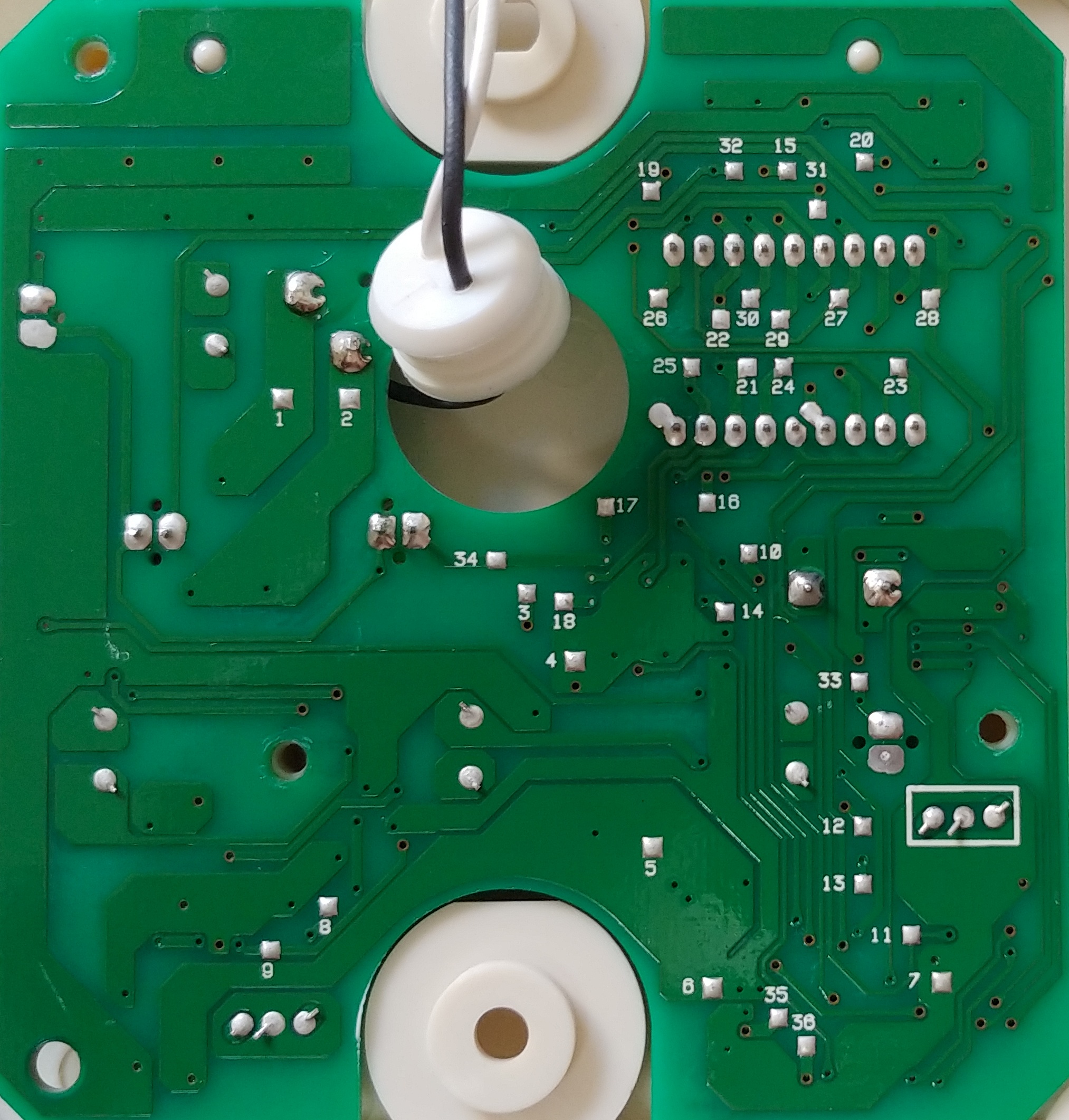
The two ICs are connected in the following way:
- IC1 P18 (pulled up to Vcc with 10K) – RA1 (10K) – IC2 P5 (TP9)
- IC2 P12 – RA1 (10K) – IC1 P13
I connected a logic analyzer to IC2 P5 and P12. My logic analyzer is pretty basic, but should be more than enough for the kind of frequencies I am expecting here. The logic analyzer connects to a PC over USB where I use the PulseView software which is a UI for Sigrok. Let’s look at the first capture:
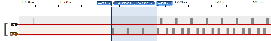
So at power up (the main unit is plugged into a socket) we have no signals and then P5 goes high for a brief moment. This is due to the pull-up via RA1 and the MCU not yet initializing and pulling the line to Gnd. Then about a second later some party starts to send data at 200ms intervals. 3 cycles later two more parties join the scheme with one party at P5 and two parties at P12 in total.
Considering that my setup was composed of a main unit, the original control panel and an another (external) control panel that I am using for the project, we can assume that P5 is the tx (transmit) line of our unit and that P12 s the rx (receive) line of our unit. For the clarity of further discussion, let’s establish a naming convention:
- Main – The main heater unit, the large box that does the heating. Has no UI.
- Internal – The control panel that is installed inside of the main unit. Still uses the same wiring as external units (in this model).
- External – The control panel that is wired externally to the main unit in parallel to the internal unit. This is the unit where we capture our signals.
Consider that Main can’t know which unit is installed where and that the Main can support, at least, one additional control panel.
Now let’s zoom in on one of the cycles:

We can see that a typical cycle has 3 packets. Each packet is 30ms in length. First we have a packet from Main, then 10ms of delay, then a packet from External, then 50ms of delay, then a packet from Internal and after another 50ms of delay a new cycle repeats. Further observation and sampling at other points in time revealed that 50ms is basically 10 + 30 + 10ms, an unused slot. It seems that each 200ms cycle has 5 30ms packet slots with padding. The first slot is used by Main and that leaves 4 more potential slots for control panels. Let’s zoom in on one of the packets:
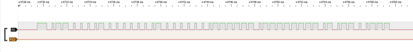
We can see a long pulse at the beginning followed by sets of long and short pulses. We can see 48 falls and 48 rises after the initial pulse. The falls set the clock and the position of the rise could determine the symbol. Given that 48 divides cleanly by 8, we might be looking at exactly 6 bytes of data.
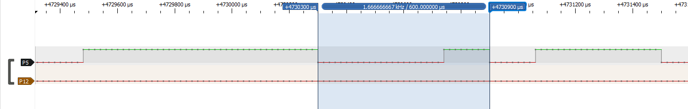
Each symbol is 600 micro seconds (us) long and the pulse ratio is 25%/75% or 75%/25% depending on the symbol. This scheme is similar to what is used in IR remote controls or RF ASK modulated signals except this is not modulated. I call this “variable pulse length encoding”. I tried to match this to popular digital protocols such as UART, I2C, SPI, etc. but it didn’t match with any of those. At this point I decided to write a decoder plugin for Sigrok to help me reverse the protocol further.
Protocol decoder plugin
Writing a decoder for Sigrok was quite enjoyable. It is done in Python, just follow the HOWTO. I pushed the code to github as rinnai-control-panel-sigrok-pd. You can grab it and add it to your Sigrok decoders list, which you can then use in the PulseView UI or on the command line with syntax such as:
sigrok-cli.exe" -P rinnai-control-panel:data=P12:bit_numbering=lsb -P rinnai-control-panel:data=P5:bit_numbering=lsb -A rinnai-control-panel=packet --protocol-decoder-samplenum -i input.srThis is how it then looks in the UI:
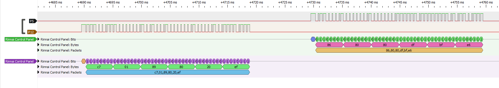
At this point I was not sure about bit numbering (lsb or msb first) and about which symbol is which bit. I was able to deduce it in the next step. The decoder has parameters that allow it do output all the different options.
Reversing the protocol
Next I captured many different scenarios; on, off, all the temperature values, has priority, no priority, heating, etc. I then matched the data with the actual states. This was a lengthy process, so I will not describe it step by step, instead I will just summarize the end result.
At the cycle level, a lot remains a mystery. The control panels seem to automatically negotiate their slots and ids. During certain reboots everything remains the same, but during others the control panels would show up at different slots and using different (what I believe are) ids. It is possible that the logic of assigning slots happens inside the PLC IC.
With regards to which panel has priority, the MCU of the panel does know if it has priority or not and visualizes that with a LED, so it should be possible to know that from the protocol. So far I wasn’t able to figure out how to check that. If you have an idea how slot assignment or id allocations work, please share. I would also be happy to obtain your captures and use them to expand the parser.
Another interesting observation about how the bus works, if you hold the tx line high then you signal that you want to talk. No other component will send packets then. The presence of a pull-up on the tx line in each panel creates (an intentional) situation that if one of the panel MCUs dies and stops pulling the signal low then the entire bus shuts down.
At the packet level:
- Each packet is 6 bytes.
- The bits are sent lsb first.
- The symbol with the longer HIGH pulse is 1.
- The last byte is xor of the first 5 bytes.
- The msb in each byte is an odd parity bit.
- We are left with five 7-bit values for data.
The properties above were determined mainly by monotonically incrementing temperature values and looking at the packets.
Furthermore:
- The state is fully determined by Main.
- The panels only seem to send button presses. They do not run any core functionality of the device.
For me, the last point is reassuring as this means that a bug or damage at the control panel should not cause anything that you cannot already do to the panel with your finger.
Structure of main unit packet
- First byte, first nibble (the most significant one): some value that is function of who is currently has priority.
- First byte, second nibble (the least significant one): fixed “0x7” meaning that this is data from main.
- Second byte is a bit mask. 0x40 = device is on. 0x08 = secondary temp scale used.
- Third byte, first nibble is a bit mask. 0x1 = heating water (“in use”).
- Third byte, second nibble: temperature code.
- Forth byte, first nibble: some value that is a function of who we have on the bus.
- Forth byte, second nibble: fixed “0”.
- Fifth byte: fixed 0x20. Perhaps error codes will go here if any.
Temperature codes
My heater can be set to the following temperature values:
35°C, 37, 38, 39, 40, 41, 42, 43, 44, 45, 46, 47, 48, 50, 55, 60
Note that 36°C, 49, 51-54 and 56-59 are not an option. Valid values between 37°C and 60°C have codes 0 to 14 respectively. 35°C is special in that it also has a code of 0 (like 37°C) but an additional bit is then set in another location (different scale?).
It is possible that your device has a different temperature scale or different codes. Please provide annotated captures if you can, so that I can update the decoder.
Structure of control panel packet
- First byte, first nibble: fixed 0 meaning that this is data from a control panel.
- First byte, second nibble: some value that identifies the sender, same between bus re-orgs.
- Second byte is a bit mask. 0x01 = on/off pressed. 0x04 = priority pressed.
- Third byte is a bit mask. 0x01 = temperature up pressed. 0x02 = temperature down pressed.
- Forth byte, first nibble: some unknown value that changes from time to time.
- Forth byte, second nibble: fixed 0xf.
- Fifth byte: fixed 0xbf.
Status review
Now that we understand many of the bits in the protocol, we can already construct a device to read the state of the system such as whether it is on, which temperature is set, whether it is heating right now, etc. The real ROI, however, will happen when we are able not just read the values but to change them as well.
Connecting
Because some aspects of the protocol (mainly ids) are still a mystery, and since we don’t want to send invalid data on the bus, it would have been problematic to try and generate packets from scratch myself. I decided to stick to modifying only the bits I understand, put myself as a proxy on the tx line and when needed simulate button presses by toggling the relevant bits in the packet. So the plan is basically to let the original MCU keep doing it’s job and then make on the fly modifications to the signal.
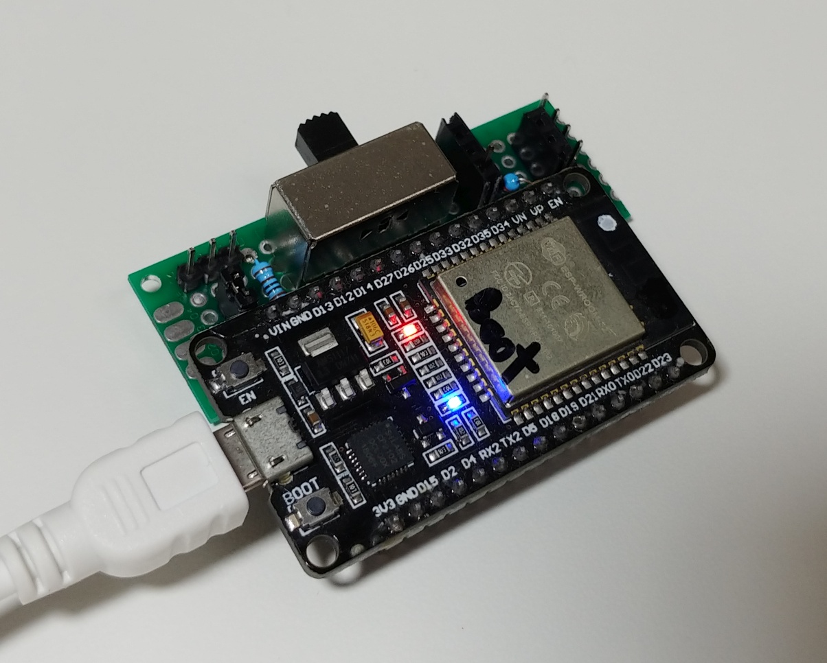
My end goal is to integrate this modified panel with my home network and with Home Assistant. My usual go to module for such cases is the ESP32. The main benefits are the built-in Wi-Fi support, the great ecosystem, support for the Arduino framework and the low cost.
The ESP32 operates at a 3.3V logic where our panel is at 5V. This would require some circuitry to drop the signal level to the lower voltage. Fortunately, 3.3V logic levels are valid 5V levels which makes life for us easier.
Let’s take a look at how the data lines in the panel are wired originally.
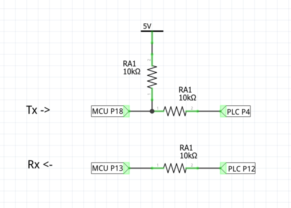
There are two different points where we can connect to the rx and three different positions for the tx. When planning to connect to this existing circuit, we have to consider the following:
- Location on the PCB and practicality of soldering wires there.
- The risk of anything getting short-circuited in the new circuit.
- Dropping the signal to 3.3V logic.
Due to these various constraints, I decided to implement the following modifications:
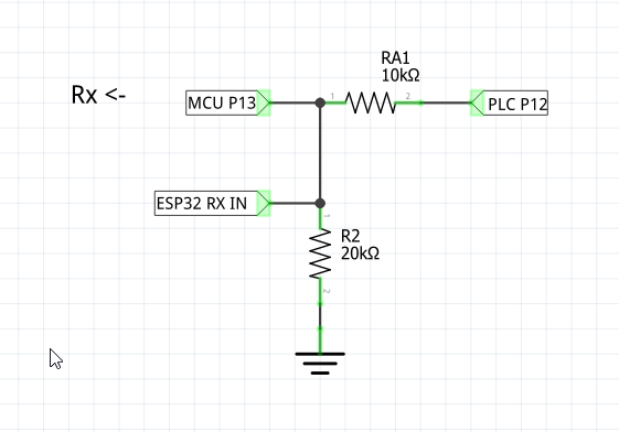
As you can see, the rx side was easy. I added a resistor to ground on the signal forming a voltage divider using the already existing 10K RA1. This drops the signal to a 3.3V level for both the ESP32 and the MCU, however, as mentioned before, this is still per-spec for the 5V TTL logic the MCU uses. Please note that if you are considering to use one of the common logic level converter modules here, you need to connect to the signal before the resistor, on the PLC side, otherwise the resistor will prevent the converter from working properly.
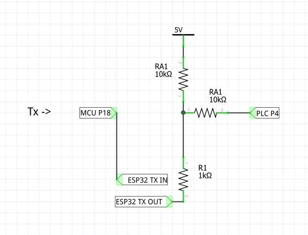
The tx signal is trickier. The 5V pull-up complicates things for us. I could disconnect it completely and replace it with a 3.3V pull up or I could put a MOSFET on that side, but instead (at least for this iteration) I decided to just wire the ESP32 there with a series resistor (for some short circuit protection). This is not the best way as it is out of spec for the ESP32 but it seems to work. The problem is that the ESP32 will need to pull down a 5V level coming from the pull-up when we need to drive P4 low. I guess it works ok because the currents are very small. There is some debate on whether the ESP32 is 5V tolerant. The official answer is that it isn’t. I am planning to make few additional iterations of the circuit and to post a follow up.
For “tx in” we can just connect P18 to the ESP32 pin. This is because P18 turned out to be open collector. This actually makes sense if you recall the external pull-up. So we just need to enable the internal pull-up on the “ESP32 TX IN” pin.
This plan leads us to the following modifications of the control panel PCB:
The trace from MCU P18 is cut and copper is exposed by removing some solder mask with a piece of sand paper. Wires are also soldered to Gnd, 5V and 12V sources. The additional circuit is constructed on a perfboard with connectors for the ESP32 and the cables we soldered to the control panel.
I also added a DPTT (double pole triple throw) switch, which can short TX IN and TX OUT or send them to ESP32. I didn’t use it much in the end. The bypass didn’t work well unless Gnd is also disconnected so it was of limited use.
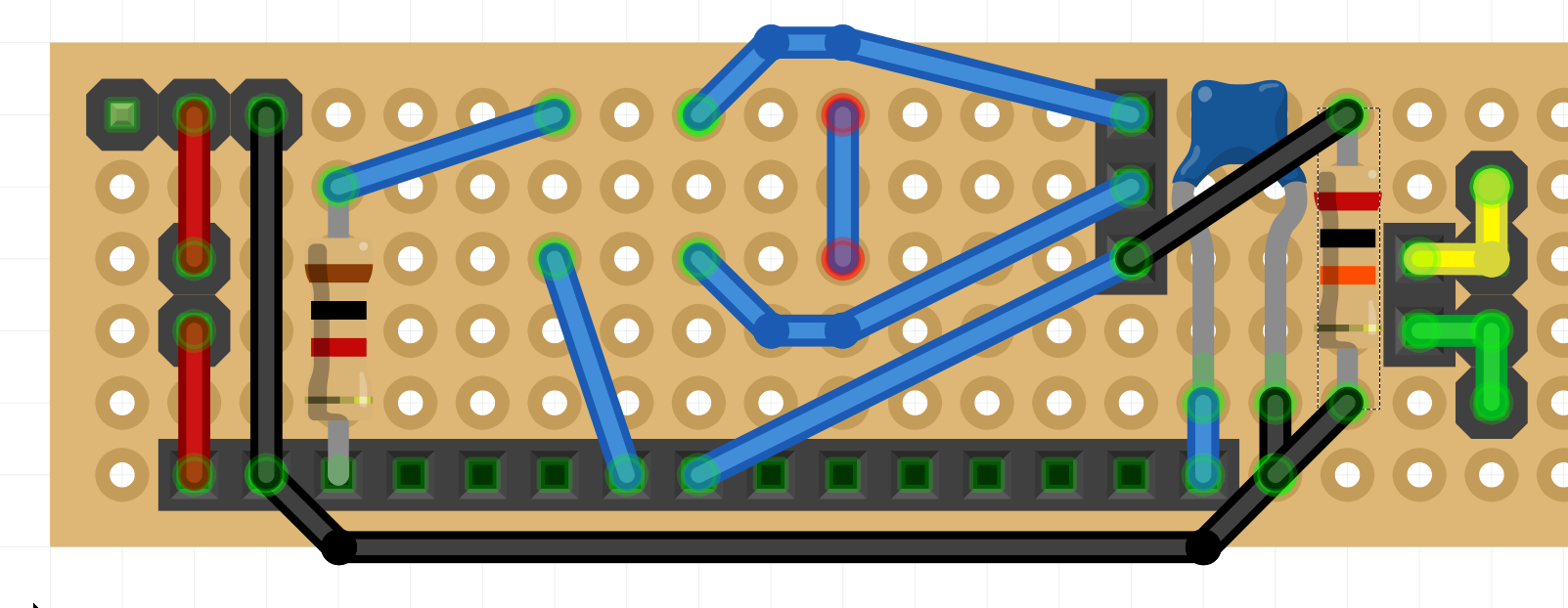
The capacitor is on the EN pin of the ESP32 and helps it boot into programming mode. This might be specific to the ESP32 module I used and might not be needed in other cases. The yellow/green connector on the right is just for connecting the cable of the panel to the cable of the main unit. Once wired this looks more or less like this:
Firmware
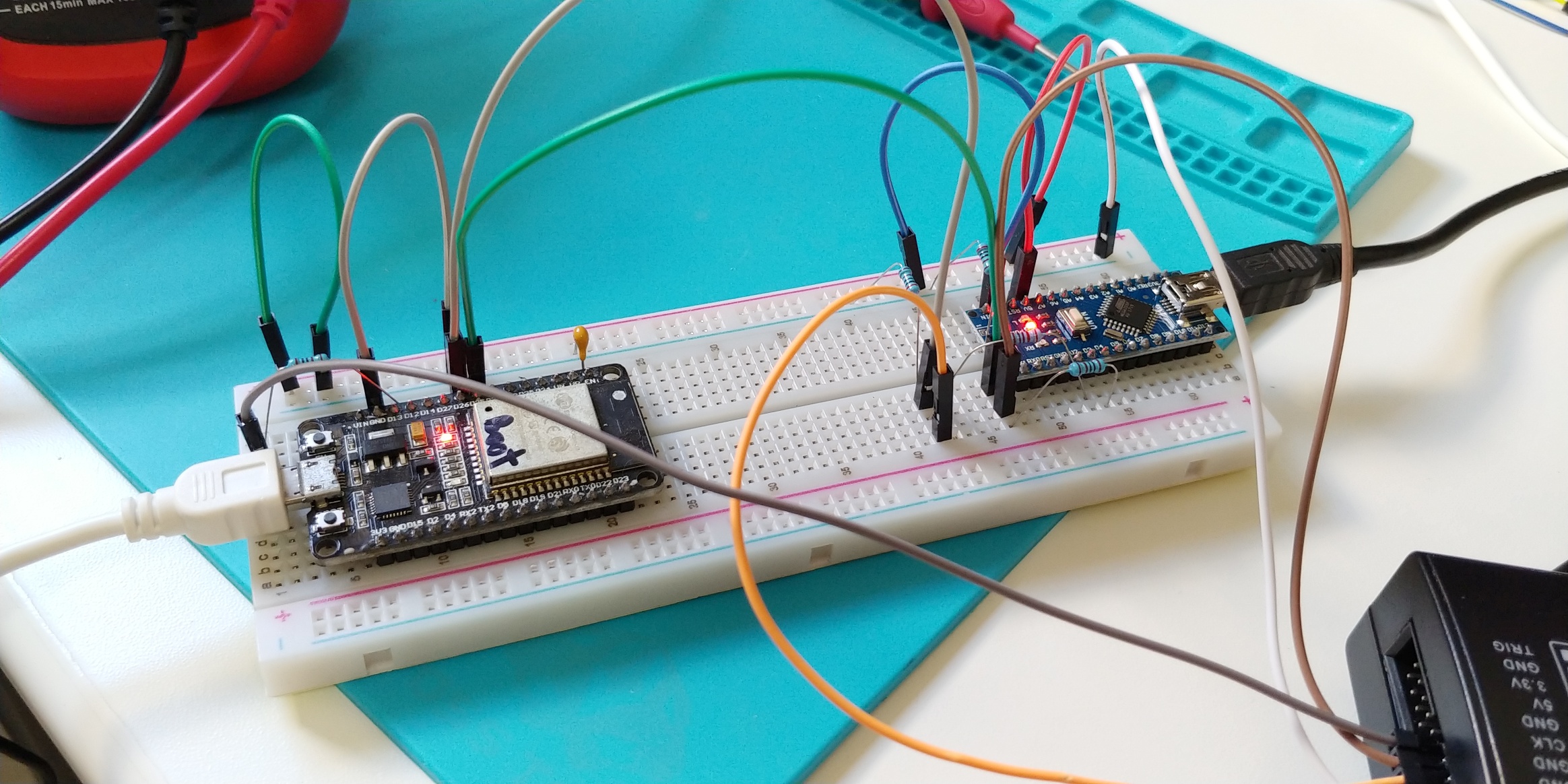
To write the firmware for the ESP32 comfortably, I made a simple mockup of a control panel using an Arduino Nano and a short program. This allowed me to develop the software at my desk without affecting the Rinnai.
The firmware is available on github at rinnai-wifi so I will not get into a line-by-line review here. It was developed using PlatformIO as the IDE. It has these following components for infrastructure:
- IotWebConf as WifiManager and web config.
- arduino-mqtt for MQTT
- ArduinoJson for JSON
- RemoteDebug for debugging over the network
- and the built-in ArduinoOTA for over the air updates
For business logic we have RinnaiSignalDecoder to convert the digital signal to packets, RinnaiProtocolDecoder to parse the packets into properties and RinnaiMQTTGateway to interface it all to MQTT Discovery for HA. Specifically, it implements the HVAC (climate) spec of Home Assistant.
In the RinnaiSignalDecoder class there are two sets of functionality that are worth mentioning. First, it uses interrupts to capture the incoming pulses and then uses FreeRTOS tasks to parse the pulses into bits, bytes and packets. While doing that, in normal operation it will just be a pass-through proxy. Second, when there is need to make an on the fly modification to the signal, it will stop passing through the signal and will unblock a high priority task to bit-bang the modified packet. The modification happens at the exact timing using packet data of a previously sent packet resulting in accurate content and timing for any bits we don’t touch.
As with any other “iot” device, we need to consider and discuss security. This device is not meant to be exposed outside of the home network. In fact, I would even say that it should not be exposed. Normally, Home Assistant systems are local, so that works fine. The only potential security vector I am aware of is that if somebody malicious gains access to your network and your HA or your MQTT server, he will be able to set the temperature to an unpleasant level. To counter this possibility, the firmware limits the maximum temperature range to 48°C. Normally, the heater can go up to 60°C. This also simplifies temperature code to temperature value conversion logic in the firmware. For additional protection, over the air updates are password-protected and a button press can be required to allow OTA updates. There is no point to discuss any attacks that need physical access because physical access already allows full temperature control.
Summary
It was an interesting project I learned a lot from, but more difficult than I expected. In retrospect I would recommend trying the official Rinnai Wi-Fi module first unless you are really interested in DIY electronics. Curious to hear if anybody out there has done anything similar, perhaps using another approach. LMK.
Pingback: Making a proper adapter board for the "smart" WiFi Rinnai | Arik Yavilevich's blog
Pingback: Convention for compile time configuration of PlatformIO projects | Arik Yavilevich's blog
Hi just want to say what a good reverse work you have done on this, i have been looking for something like this for years, I’m going to do this next week, thanks Dave
Hi David,
That is awesome. If you find any additional info please share.
Hi Arik
I will get a wifi unit off rianni as I do a bit of work with them and I will have a look at the unit, but can you tell me why you did not go with option 1?..
Cool.
“option 1”? You mean integrating at the 12V power line communication (PLC) bus? Seemed like more work. You would need to be able to fully reverse the protocol for that and have more complex circuitry. Was easier to “piggy-back” on the existing hardware.
Hi Arik.
You were absolutely right to avoid using the official Rinnai’s wi-fi controller. Control-R is a defective product. The phone app reviews actually also apply to the controller itself because it loses wi-fi connection very often. It makes the app useless.
I have this controller installed in my system, and it makes difficult to use the on-demand hot water recirculation feature.
I have a question. Is there a way to hardwire the on-demand recirculation through an external push-button? This would by-pass the wi-fi channel and would use a simple circuit to switch on and off the recirculation. The model that I have is RUR199iN.
Do you know if there is any solutions for that?
Hey Michael,
I understand your feedback, but your WiFi issues might also result from the location of your WiFi router/AP relative to the Control-R, from the quality of your router/AP or from the density of WiFi communication in your area. Not saying Control-R is always good, just playing devil’s advocate. You might want to test those issues. Perhaps move Control-R closer to the AP or move the AP closer to the Control-R and try again.
Do you currently have a re-circulate button on your heater or is Control-R the only way to activate re-circulation?
Regarding alternatives for WiFi. There might be other, more advanced wired Rinnai control panels that you can connect to the heater just like you did with the Control-R and those panels might have a recirculate button. Try to call a Rinnai seller in your area and ask about that. That would be fully wired.
Another option would be to try Rinnai’s official re-circulation button. It is wireless but it is not WiFi so it might work more reliably. See the following resources:
https://www.rinnai.us/tankless-water-heater/accessories
https://www.youtube.com/watch?v=V7BcZZ_Ybjs
Let us know what you decide to do and how it goes.
Arik, thank for looking into the matter. I have been struggling with this Control-R module for almost a year and explored multiple options.
Moving the module closer to the WiFi router was the first alteration that I made. It is now literally one foot away from it. I also have three other devices for home automation that work perfectly with existing router and WiFi density.
I’ve been in contact with the manufacturer as well. The only way to use the on-demand feature is through the Control-R. There are several devices for that (as shown in the links you attached) and all of them need Control-R to communicate with the heater. The unit itself does not have such button.
I like your idea to use the official push button from Rinnai. You are right, it uses Zigbee protocol which could happen to be more reliable in this particular device than regular WiFi. It is probably worth a try but it costs around $80 delivered, with no guarantee that it will work better than the smartphone app.
I was hoping to find a more reliable solution and was curious if anyone had applied it in practice.
Hey, glad to take a look at it. Interesting challenge.
Reading what you described about having WiFi issues at such a close range is a bit puzzling to me. I can see how it can be frustrating. I personally don’t have a unit with re-circulation or a Control-R device so it is all science fiction to me.
I think that trying the Zigbee button is the most cost/time effective thing you can do. Perhaps if it doesn’t work you can return it.
If you have electronics skills you can try to alter the system. This can be done at the Control-R level and possibly in the internal electronic board of the heater. But this approach is risky and time consuming so be warned.
Wow, nice work! Want to sell me the hardware for a few hundred bucks? I can write the software. Control R is terrible for lots of reasons, wish I had more control of my water heater.
Hey Samuel,
Glad you like the project. Unfortunately I don’t sell the hardware for several reasons including; liability, variety of Rinnai models and the difficulty of international shipping.
Maybe you can get the right panel for your device locally and use a local electronics technician to make the changes for you.
If you will need help I can do consulting for a fee or in some cases in exchange for Rinnai packet samples that will make the open source project better.
Wow. very thorough article here. Took me a while to get through ti. Thanks for posting though. I got some good ideas
Hi Arik
This is what I’ve been looking for ages great work.
Do you if this will work with the MC-100V it uses a different MCU EQ-784-V01 due to the LCD and the TI powerline chip is a TMS57997B, Hopefully, the protocol is the same. As this is the unit that will go to 65C and easily to open. I also have MC-91Q-2A and BC-100V both are only max Temp 50C
Regards
Paul
Manual
Hey Paul,
Glad you like the article.
I believe they all have the same protocol, which is what allows them all to work together. Each might have slightly different packet content though.
I suggest you figure out where the internal tx/rx lines are and try to capture the signal.
I am not sure if TMS57997B is the power IC though. Could be just an MCU to do some function on the board. What made you think it is the PLC IC? Can you send clear photos of your board?
Regards, Arik.
Hi Arik
What’s the best way to send the photo,s to you?
Regards
Psul
You can just post a link here or you can send me privately. I will send you my email address.
Hi
Can you provide us this the ardunio codes?
Of course. There is already a link to github in the article.
I will include it here again for convenience: https://github.com/ayavilevich/rinnai-wifi/
Hi Arik,
Thanks for your quick reply.
Can you tell me which logic analyzer did you used?
And a reference link where I can buy one online.
I used a LHT00SU1 Logic Analyzer. You can google it to find stores.
Hi Arik,
From this picture you have posted
I can see that you have connected 6 wires to the Rinnai PCB and you have mention that 3 of these wires are Ground, 5V and 12V.
Can you tell me the functions of each wires?
Hi krish,
The other three are: esp32 rx in, esp32 tx in, esp32 tx out. See section called “Connecting” for more details.
Hi Arik
Can you post a picture with labelling each wires?
And I want to know what is the purpose of the 12V line?
I’ve been looking for exactly this for the Bosch unit I own.
I’ve not got a spare controller to pull apart yet however it is *very* curious to me that Bosch have
Temp up ,
Temp down
Priority
And an digit display showing values.
Have you seen any work on the Bosch protocol or control units ?
In my case I want to analyse total hot water consumed. The display can be put into “maintenance mode” which gives the instantaneous flow rate but it isn’t accumulated on the machine (or not offered in the diagnostics anyhow)
Be fascinated if you happen to know anything about Bosch
Hi Michael,
Indeed the buttons seem to be similar to the ones on a Rinnai control panel.
I have not seen any info on Bosch units. How do you put the display in and out of the “maintenance mode”?
How is the control panel connected to the main units? Same two wires as with the Rinnai?
Hey
I am studying your project to modify other remotes / controls. I can’t figure out what the variables are doing:
heaterPacketCounterlocalControlPacketCounter
remoteControlPacketCounter
They are constantly increasing and not decreasing, the conditions where they are present are always met
What are they needed for?
Hi Anatol,
These are counters for various packet sources. You can use them to check if you got any packets from that source or not.
Hey Arik!
I have the exact same control unit and i’m trying to make this project.
I’m having some trouble identifing the parts… Would you help me identify each pin you soldered on the board?
Thanks! Very nice project!
Hi Gabriel,
Please see section “Connecting” for the relevant information. You need to solder some points on the PCB and cut a trace. This picture https://blog.yavilevich.com/wp-content/uploads/2020/08/Rinnai-Control-panel-PCB-patch.jpg shows the result.
LMK if you have any questions after reviewing the info.
What an amazing you have done!!!
I also have the RUR1199iN with the Control-R 2.0 with the recent firmware upgrade. I have HomeAssistant and HomeBridge running with the Rinnai Homebridge Rinnai Control-R Plugin (homebridge-rinnai-controlr v1.0.14).
The Rinnai firmware plugin failed and bricked my ControR. Rinnai sent a new onw in 4 days. before the firmware upgrade I did gel lots of “Not connected” msgs.
It seems to be rock solid now and has not happened once since the new unit and firmware update. I did move the controller to within 18′ of my Wifi as so I had a better signal.
I cannot do much but I have it set for turning on at scheduled times of the day for specific periods of time. I can change temps instantly check current stats like flow and input and out put temps and flow, that refreshes almost instantly without any issues from the phone app.
The better part is that I can now set up much more complex automations in HomeBridge and they work!
I installed a 150 insulated recirc loop and when we get up we have instant hot water at every tap and the recirc is only on for 3 min to do that. At any other time of the day it is “Hey Siri, hot water on” and it runs a 39GPM recir for 3min.
So the point is that things may have changed for some and although this the work you have done is a marvel. It is way over my head(Like reading a great spy novel) and other folks may still be able to get what they need simpler.
It would be great if there could be a plugin made for Home Assistant that pulled in all the data and allowed even better control.
Two other observations from my installation. Installing a dedicated, insulated loop made the Rinnai practical. No more running the tap for 2-3 min every time we need hot water at the other side of the house. The unit operates very differently(Economically) with a dedicated loop vs having the useless/marketing “Recirc” valve. We now use alot less water/gas(Canada cool temps)
The other was the vibration noise from the pump every time the water comes on that you can feel through out the house. I installed the unit on a 7′ 2×10 that sits on the concrete floor and the top is vibration isolated from the wall. The unit is now virtually silent.
Your project was great to read.(all I will be capable of)
Great write up! I stumbled across your write up since I’m trying to detect the recirculation state of my RUR199iN. I have the “dumb” MC-195T external controller and hooked up a smart dry contact relay to be able to “press” the recirculation button with my smart home hub. Theoretically, the hub could keep track of the recirculation state by tracking button presses, but it’s bound to get out of sync in practice. So I just need to figure out a way to detect the current state of the recirculation. Did your tinkering reveal any way to just detect that state?
Hey Justin,
My Rinnai device is not capable of re-circulation so I never had this dilemma.
The data is probably there in one of the messages. Should be easy to find it using trial and error once you are able to capture the packets.
If you are comfortable making changes to the control panel and using a logic analyzer then it could be a great project. The modification for merely observing the data should be simpler than creating/editing messages. Please post your findings if you discover any new details.